Thin-Gauge Electrical Steel Selection for High-Frequency Magnet-Free Motors: NO20, NO25, and Stacking Tech RFQ Guide
Compare NO20 and NO25 thin-gauge electrical steel for magnet-free motors. Review loss data, joining trade-offs, and the RFQ checklist before requesting a quote.
The short answer: Shortlist 0.20 mm (NO20) and 0.25 mm (NO25) thin-gauge electrical steel when high-frequency core loss constrains a magnet-free motor. Choose the specific mill grade, coating, and joining process together. Thickness alone does not establish finished-core loss, rotor strength, motor efficiency, or cost. Compare candidates at the same flux density, electrical frequency, temperature, and duty cycle before approving a stack.
This engineering procurement guide helps global drivetrain buyers and motor engineers compare synchronous reluctance motors (SynRM) and externally excited synchronous motors (EESM), request comparable evidence, and prepare a lamination-stack RFQ.
Published / last reviewed: October 29, 2026. Region/language: Global / English. Scope: Radial-flux SynRM and EESM stator and rotor sourcing. Evidence limits: This is a public-source selection framework with reproducible calculations, not an independently tested motor comparison. It supplies no universal speed limit, IE5 certification, bond-life guarantee, or approved rotor design. Supplier data and program validation remain necessary.
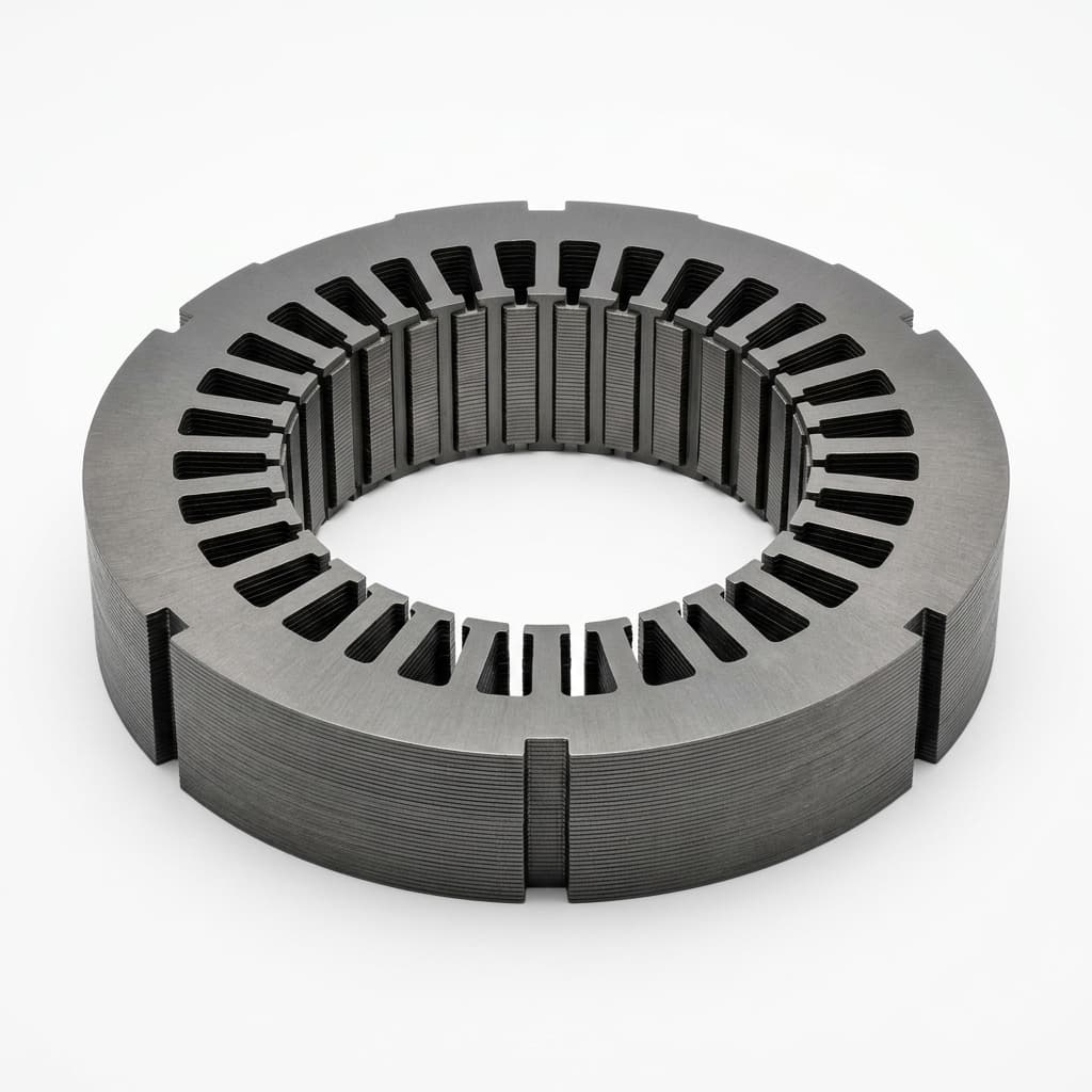
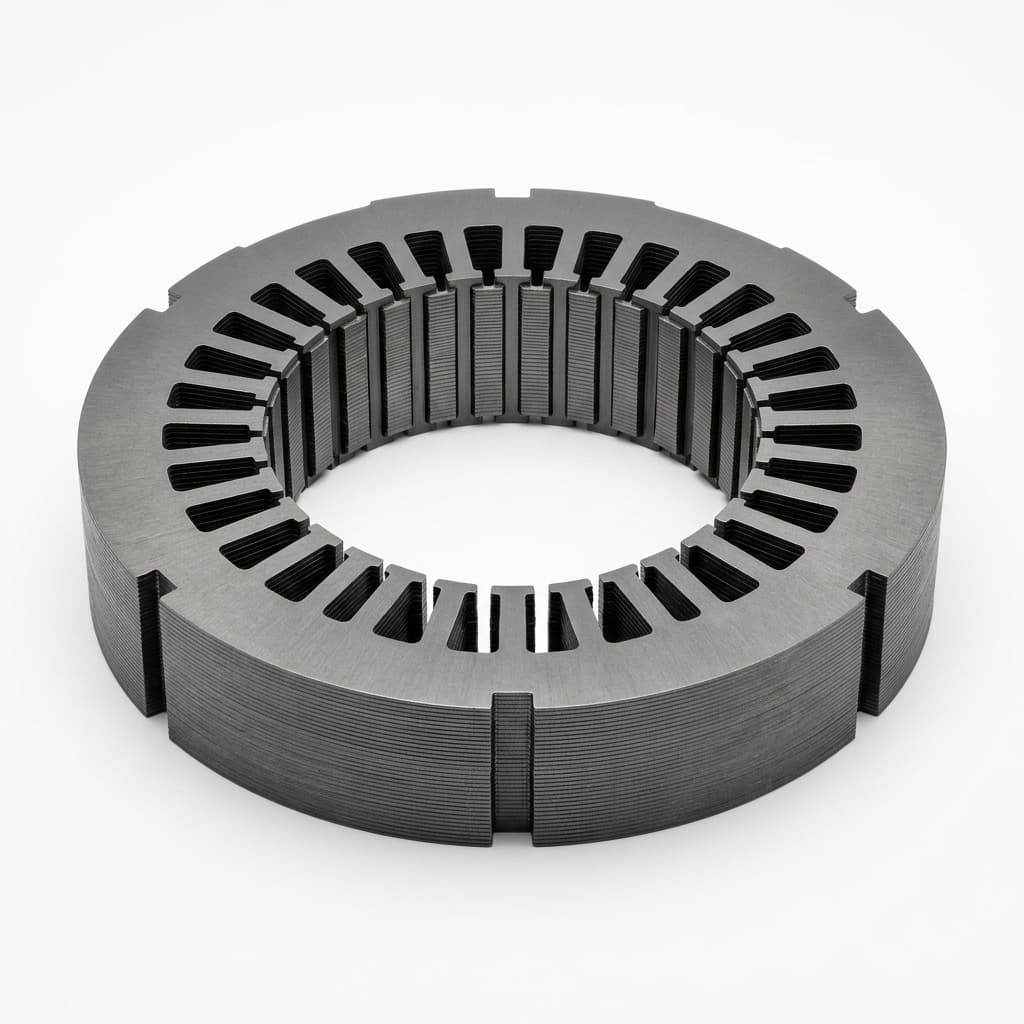
Product illustration of a lamination stack; the image does not establish steel thickness, material grade, or tested performance.
For related engineering and sourcing topics, see our automotive traction motor sourcing guide, brushless excitation system manufacturer guide, 800V SiC inverter insulation screening guide, hairpin winding engineering overview, and IE5 SynRM vs. induction efficiency comparison.
Preparing an RFQ? Submit your core drawing, speed profile, and target frequency for a feasibility discussion.
1. The Physics of Iron Core Loss at High Electrical Frequencies
Rotational speed does not determine electrical frequency without the pole count. For a synchronous machine:
f_e [Hz] = pole pairs × speed [rpm] / 60
Example: 4 pole pairs × 15,000 rpm / 60 = 1,000 Hz
This is the stator fundamental frequency, not the inverter switching frequency. PWM and slotting harmonics need separate treatment; do not substitute switching frequency for the fundamental in a material loss table.
What the thickness calculation actually predicts
For a thin sheet with sinusoidal, approximately uniform in-plane flux, the ideal classical eddy-current loss per unit volume is:
P_classical / volume = π² × d² × f² × B_peak² / (6 × resistivity)Here, sheet thickness d is in metres, frequency f in hertz, peak flux density B_peak in tesla, and resistivity in ohm-metres. The result is W/m³; divide by material density in kg/m³ to obtain W/kg. At equal resistivity, flux density, and frequency, the thickness-only ratios relative to 0.35 mm are:
0.20 mm: (0.20 / 0.35)² = 0.3265 → 67.3% lower classical eddy loss
0.25 mm: (0.25 / 0.35)² = 0.5102 → 49.0% lower classical eddy loss
These are reproducible model calculations, not measured total-core-loss reductions. Hysteresis, excess loss, material chemistry, cutting stress, rotational flux, and inverter harmonics are outside this simplified ratio. Total motor loss also includes copper, mechanical, and other losses. Request measured loss curves and a validated machine model rather than converting these percentages into an efficiency promise.
2. Why Magnet-Free Topology Changes the Evidence You Need
Synchronous reluctance motors: evaluate flux barriers and ribs
A SynRM creates torque from the difference between direct-axis and quadrature-axis inductance. In the simplified unsaturated model, T = 1.5 × pole pairs × (Ld − Lq) × id × iq. Flux barriers improve magnetic saliency, while the remaining steel ribs carry mechanical loads.
A thinner sheet does not automatically make a rib safe or unsafe. Stress depends on rotor radius, barrier geometry, interference fits, material direction, temperature, and speed. Ask for geometry-specific electromagnetic and structural analysis, hot mechanical properties, fatigue assumptions, and the agreed overspeed test. Bonding can support stack integrity but cannot replace a verified in-plane load path through each lamination.
Externally excited synchronous motors: separate stator and rotor losses
An EESM adds rotor field-winding copper loss and an excitation system. The ideal synchronous fundamental field is stationary relative to the rotor; slotting, inverter harmonics, and transients can still excite rotor iron loss. Specify stator and rotor thermal evidence separately, including field current, cooling, and the actual inverter waveform. Do not apply a stator 1,000 Hz material figure directly to the rotor as its fundamental loss.
3. High-Frequency Electrical Steel Grade Comparison
NO20 and NO25 identify thickness families, not complete purchase specifications. Record the producer's full grade and coating code. The six examples below are from the thyssenkrupp powercore traction grade table.
| powercore traction NGO grade | Thickness (mm) | Maximum loss at 1.0 T / 400 Hz (W/kg) | Minimum polarization at 5,000 A/m (T) | Minimum yield strength (MPa) |
|---|---|---|---|---|
| 020-130Y320 | 0.20 | 13 | 1.59 | 320 |
| 020-130Y350 | 0.20 | 13 | 1.59 | 350 |
| 020-150Y320 | 0.20 | 15 | 1.59 | 320 |
| 025-130Y420 | 0.25 | 13 | 1.61 | 420 |
| 027-140Y420 | 0.27 | 14 | 1.61 | 420 |
| 035-180Y400 | 0.35 | 18 | 1.61 | 400 |
Source conditions: producer catalogue limits, not our measurements; yield strength is in the rolling direction at room temperature. These values do not establish 1,000 Hz loss, hot strength, coating suitability, or finished-core performance. Confirm the current signed datasheet and supply availability with the mill.
RFQ implication: Compare complete grades at common operating points; do not rank every NO20 ahead of every NO25. Request 1,000 Hz data explicitly if your duty cycle needs it. Identify the test method, waveform, sample preparation, temperature, and whether each value is guaranteed or typical.
Standards boundary: The IEC 60404-8-4:2022+AMD1:2026 catalogue scope covers nominal thicknesses beginning at 0.35 mm; it is not a blanket delivery specification for 0.20 or 0.25 mm material. For thin grades, agree the applicable EN 10303 designation or producer specification, edition, and additional contractual guarantees. A delivery standard is also distinct from the method used to measure high-frequency loss.
4. Technical Architecture: Lamination Loss Mechanisms & Stacking Methods
The diagram summarizes three separate decisions: ideal thickness scaling, insulation continuity after joining, and geometry-specific rotor validation. Read it as a conceptual aid, not measured loss or strength data. On small screens, scroll horizontally to read the labels.
Diagram takeaway: thinner sheets reduce the ideal classical eddy component; joining still needs electrical and thermal qualification; rotor ribs still need structural analysis and overspeed evidence.
5. Lamination Joining Topologies: Backlack vs. Welding vs. Interlocking
Choose the joining route with the coating supplier and core manufacturer. Backlack is a self-bonding coating system; a supplier's spot adhesive or impregnation route should not be assumed equivalent to full-surface bonding.
| Joining route | Main selection trade-off | Evidence to request before approval |
|---|---|---|
| Full-surface self-bonding varnish (Backlack) | Avoids joining punctures; adds coating, curing, and aging requirements | Approved cure window, bond strength after aging, stack loss, and thermal resistance |
| Laser stitch or seam welding | Fast local retention; heat and conductive bridges can change losses | Weld location and process window, dimensional inspection, and before/after core loss |
| Mechanical interlocking | Integrates stacking into stamping; local deformation and contacts need evaluation | Interlock geometry, insulation checks, finished-stack loss, and retention tests |
| Through-core tie rods or external cleats | Provides clamping but affects packaging, load paths, and possible current loops | Fastener insulation, preload retention, electromagnetic review, and balance report |
| Resin impregnation | Bonding and void filling depend on penetration and chemistry | Penetration evidence, cure records, coolant compatibility, and thermal cycling |
| Spot adhesive bonding | Limits adhesive coverage but differs from full-surface bonding | Coverage inspection, hot bond strength, flatness, insulation, and aging results |
There is no universal percentage penalty for a weld or interlock, and no joining method guarantees zero added loss. Compare processed stacks of the same geometry, material lot, and excitation conditions. Separate losses caused by cutting, joining, and assembly wherever the test method allows.
Coating evidence matters: voestalpine's February 2026 technical terms, page 10 state that insulation resistance is not guaranteed for its C-3 and Backlack systems solely from layer thickness. They also distinguish C-5 as an inorganic/organic system. Therefore, neither “infinite resistance” for Backlack nor a universal annealing temperature for C-5 is an acceptable RFQ assumption. Obtain the actual coating data and processing instructions.
6. Manufacturing, Tooling, and Prototyping Realities
Specify burr and clearance acceptance with the process owner
Ask the stamper to propose cutting clearance for the actual alloy, thickness, geometry, coating, and tool. State whether clearance is per side or total. Require a burr measurement method, sampling locations on teeth and ribs, measurement uncertainty, and an acceptance limit agreed on the drawing. A small burr-height number alone does not prove that the assembled stack remains insulated.
Evaluate first-off samples and samples near the agreed maintenance interval. Request tool-wear records and stack-loss evidence rather than prescribing one press type, carbide grade, or regrind interval for every supplier.
Prototype cutting routes are not interchangeable
- Laser cutting: Review edge condition and heat effects, especially around narrow bridges. Agree whether heat treatment is permitted by the grade and coating supplier; a generic furnace recipe can damage a coated part.
- Wire EDM: Inspect recast layers, dimensional accuracy, and electrical bridging if sheets are cut as a pack. Qualify cleaning and drying for the selected dielectric.
- Photochemical etching: Avoids a mechanical cutting load but still requires checks for undercut, rib dimensions, surface condition, and material/coating compatibility. It does not guarantee production-equivalent magnetic properties.
Compare prototype and production routes explicitly. Tooling price and lead time depend on drawing maturity, die scope, volume, and inspection requirements; obtain itemized quotations instead of relying on a universal cost range.
7. 2026 RFQ & Supplier Audit Checklist: Thin-Gauge Core Sourcing
Use this ten-point checklist to make competing quotes comparable. Values not yet defined by the design owner should remain open actions rather than invented acceptance limits.
- 1. Grade traceability: Full producer grade, nominal thickness, coating code, delivery condition, applicable standard/specification edition, and lot certificate.
- 2. Magnetic loss evidence: Common flux/frequency points, including 1.0 T / 400 Hz and 1.0 T / 1,000 Hz where relevant; measurement method, temperature, waveform, and guaranteed versus typical status.
- 3. Rotor structural basis: Drawing revision, operating and overspeed envelope, hot strength in relevant material directions, fatigue/load cases, and validation owner.
- 4. Edge quality: Drawing-specific burr and dimensional limits, measurement method, sampling plan, and checks near the tool-maintenance limit.
- 5. Stack geometry: Gross height, net iron length, stacking factor definition, clamping condition, flatness, and tolerances after joining.
- 6. Bonding process: Named adhesive/coating system, supplier-approved cure window, process records, and hot/aged bond-strength acceptance criteria.
- 7. Coolant and service aging: Actual oil or coolant, temperature-time profile, thermal cycles, and agreed retention of mechanical and electrical properties.
- 8. Insulation after processing: Agreed surface/interlaminar resistance method where applicable, plus finished-core loss checks; do not assume a coating class guarantees the assembled result.
- 9. Prototype-to-production transfer: Cutting route, permitted heat treatment, coating compatibility, and evidence explaining differences from stamped production parts.
- 10. Commercial and quality terms: Tool ownership, maintenance responsibility, yield/scrap assumptions, minimum order quantity, lead time, inspection deliverables, and change-control plan.
Send the completed RFQ checklist and lamination CAD for a stack feasibility discussion.
8. Application Boundaries & TCO Sourcing Strategy
When to retain 0.35 mm as a candidate
Retain the baseline if measured machine loss, temperature, and duty-cycle energy meet the program targets at an acceptable cost. RPM alone cannot reject it: pole count and flux matter. Check the finished core rather than assuming that a conventional joining route is adequate.
When to compare 0.25 mm and 0.20 mm
Compare both when high-frequency loss is a meaningful constraint. Obtain common-condition loss maps, stacking factors, tooling proposals, and hot rotor data. A 0.25 mm grade can be competitive with a particular 0.20 mm grade at one test point; performance at other frequencies and flux levels needs its own evidence. There is no universal RPM at which NO20 with Backlack becomes mandatory.
A reproducible payback screen
Annual energy saving [kWh] = duty-weighted average loss reduction [kW] × annual operating hours
Simple payback [years] = incremental installed cost / annual energy cost saving
Hypothetical industrial-drive example, not test or price evidence: If validated operation later establishes an average 0.10 kW loss reduction over 4,000 hours/year, the saving is 400 kWh/year. At an assumed energy price of 0.15 currency units/kWh, that is 60 currency units/year. An assumed installed premium of 180 units gives a three-year simple payback. This excludes discounting, maintenance, and financing. Replace every input with program data; EV battery-sizing or cooling-system savings require a separate vehicle-level study.
9. Frequently Asked Questions (FAQ)
Q1: Does thinner electrical steel always reduce stacking factor and motor torque?
At equal coating thickness, thinner sheets increase the coating fraction. A simple geometric illustration is k = d / (d + 2c), ignoring burrs, roughness, and air gaps. Assuming 2 µm of coating per face gives approximately 0.980 for a 0.20 mm sheet and 0.989 for a 0.35 mm sheet. These are calculated examples, not supplier guarantees. Verify net iron length under the agreed clamping condition and recalculate saturation and torque for the design; a fixed torque penalty cannot be inferred.
Q2: Can we weld a 0.20 mm lamination stack instead of using Backlack?
Potentially, if the selected material/coating and weld route are qualified. Review conductive bridging, heat effects, dimensions, retention, and finished-core loss for the actual seam design. Compare an approved welded route with a bonded route on the same duty cycle; neither a fixed welding penalty nor a zero-loss bonding claim is justified without measurements.
Q3: Will high-strength steel and Backlack prevent rib fracture in an 18,000 rpm SynRM?
Those choices alone cannot establish safe operation. The rotor needs geometry-specific stress and fatigue evaluation with temperature, fits, tolerances, and overspeed included. Specify material direction and hot properties, then validate the complete assembly. Adhesive must not be assumed to carry an unverified in-plane centrifugal load or eliminate rib failure.
Q4: Does stress-relief annealing damage insulation or Backlack?
It can. Confirm the complete thermal route with the steel and coating suppliers before ordering. Fully processed steel, semi-processed steel, organic-containing insulation, and self-bonding systems need different handling. Do not apply one annealing recipe or infer compatibility from “C-5” alone. Request post-process magnetic, coating, and bond evidence for any approved treatment.
Q5: How do we audit a stamper's 0.20 mm capability?
Inspect representative parts from the proposed route and tool condition. Review measured burrs and rib dimensions, stack height, coating condition, joining records, core loss, traceability, and the agreed maintenance controls. Ask for hot and aged bond data when bonding is proposed, and rotor validation when the supplier's scope includes a rotating assembly. Equipment lists alone do not prove capability.
10. Sources and Evidence Limits
Public references checked: October 29, 2026. These sources support the specific catalogue and coating statements above; they do not validate our hypothetical payback example, a finished motor, or a supplier's production capability.
- IEC 60404-8-4:2022+AMD1:2026 CSV — official catalogue scope. Delivery-standard scope; the full standard is paid. Agree the applicable thin-grade specification separately.
- thyssenkrupp Steel — powercore traction for high frequencies and e-mobility. Source of the six catalogue-grade rows in Section 3, under “Electrical steel for e-mobility and high frequencies.”
- voestalpine — isovac Technical Terms of Delivery, February 1, 2026 (PDF). Pages 7 and 10 distinguish delivery/processing conditions and coating requirements. The document's printed revision governs; its URL retains an older filename.
Ready to Prepare a Thin-Gauge Lamination RFQ?
Share the drawing revision, stator/rotor scope, pole count, speed and duty cycle, inverter conditions, cooling medium, stack dimensions, and expected volume. Include existing grade and loss data if available, and identify which tests still need an owner. These inputs help define feasible manufacturing routes and the evidence needed for a comparable quotation.
Contact the Magnet-Free Motor Engineering Team for a feasibility review and quotation.
Author

More Posts

800V SiC Inverter Stress on Magnet-Free Motors: Stator Insulation, PDIV, and Bearing Protection Guide
Specify 800V SiC magnet-free motor insulation, PDIV/RPDIV evidence, and bearing protection. Compare options and use the RFQ checklist before requesting review.
Direct Rotor Oil Cooling for High-Speed Magnet-Free Motors: Through-Shaft, Rotor Spray, and End-Winding Cooling RFQ Guide
Compare direct rotor oil cooling for magnet-free motors: shaft, spray and duct options, seal and fluid checks. Use the RFQ checklist to request a design review.
Contactless vs. Slip-Ring EESM Excitation: 2026 RFQ Guide
Compare contactless inductive and carbon slip-ring excitation for EESM. Use 2026 TCO, RPM, EMI, cooling, and supplier checks before issuing an RFQ.