Contactless vs. Slip-Ring EESM Excitation: 2026 RFQ Guide
Compare contactless inductive and carbon slip-ring excitation for EESM. Use 2026 TCO, RPM, EMI, cooling, and supplier checks before issuing an RFQ.
Inductive Contactless vs. Slip-Ring Excitation in EESM: A 2026 Procurement Guide
As the automotive and heavy industrial sectors aggressively pivot away from rare-earth permanent magnets, the Externally Excited Synchronous Motor (EESM) has emerged as the premier high-performance alternative. Unlike Synchronous Reluctance Motors (SynRM), which rely entirely on magnetic reluctance, an EESM utilizes a wound copper rotor to generate its magnetic field. By precisely modulating the direct current (DC) supplied to these rotor windings, drive systems can achieve unmatched efficiency during high-speed cruising through active field weakening—all without a single gram of neodymium or dysprosium.
However, adopting an EESM architecture introduces a fundamental engineering challenge that procurement teams must carefully navigate: How do you reliably transfer electrical power to a rotor spinning at 15,000 to 20,000 RPM?
In 2026, the industry is fiercely divided between two primary rotor excitation technologies: the proven, mechanical Carbon Brush & Slip-Ring assembly, and the advanced, solid-state Contactless Inductive Exciter (often branded as In-Rotor Inductive-Excited Synchronous Motors, or I2SM). Choosing the wrong excitation method for your duty cycle can lead to catastrophic premature wear, excessive axial packaging length, or unnecessary capital expenditure.
This comprehensive guide is designed for global buyers, procurement teams, importers, and engineers evaluating magnet-free EESM platforms. It dissects the mechanics, Total Cost of Ownership (TCO), operational limitations, and supplier validation criteria for both excitation architectures to ensure your next sourcing decision is structurally sound and commercially viable.
Last reviewed: July 25, 2026. Scope and limitations: use this article as an RFQ screening and application-engineering guide for EV traction motors, commercial e-axles, high-speed industrial drives, and sealed rotating equipment. It is not a substitute for supplier dyno maps, inverter validation, EMC testing, rotor stress analysis, or warranty approval. Validate all speed, cooling, efficiency, and maintenance assumptions against your own duty cycle before award.
For adjacent sourcing decisions, pair this guide with the EESM vs. IPM procurement comparison, the SynRM vs. EESM magnet-free motor comparison, the VFD compatibility checklist, and the rare-earth price exposure forecast.
If you already have a target speed map, package envelope, voltage platform, and annual volume, send the RFQ package to our engineering sourcing team before locking the excitation topology.
1. The EESM Rotor Power Problem: Why Excitation Matters
In a traditional Interior Permanent Magnet (IPM) motor, the rotor’s magnetic flux is "free." It is permanently generated by the rare-earth metals embedded within the rotor lamination stack. While this is mechanically simple, it creates a massive drawback at high speeds: the permanent magnets generate a continuous, unavoidable back-Electromotive Force (back-EMF) that fights the stator, requiring the inverter to waste energy pushing negative current just to keep the motor spinning (passive field weakening).
An EESM solves this by replacing the magnets with electromagnets (copper windings). This allows the motor controller to actively reduce the rotor's magnetic field at high speeds, completely eliminating back-EMF drag. But this brilliant solution creates a new mechanical hurdle.
To create the electromagnet, you must inject hundreds of watts of DC power into the copper coils on the spinning rotor. Unlike the stator, which is bolted securely to the motor housing and easily hardwired, the rotor is in constant, violent motion. Transferring power from a stationary source (the inverter) to a rotating target (the rotor shaft) requires a specialized excitation interface. The two dominant solutions to this problem—slip-rings and inductive transmitters—dictate the motor's lifespan, speed limit, and maintenance schedule.
2. Method 1: Carbon Brush and Slip-Ring Excitation
The slip-ring assembly is the legacy approach to rotor excitation, adapted from over a century of alternating current generator and brushed DC motor technology. It remains the most widely deployed excitation method in early-generation magnet-free EVs (such as those produced by Renault and BMW).
How It Works
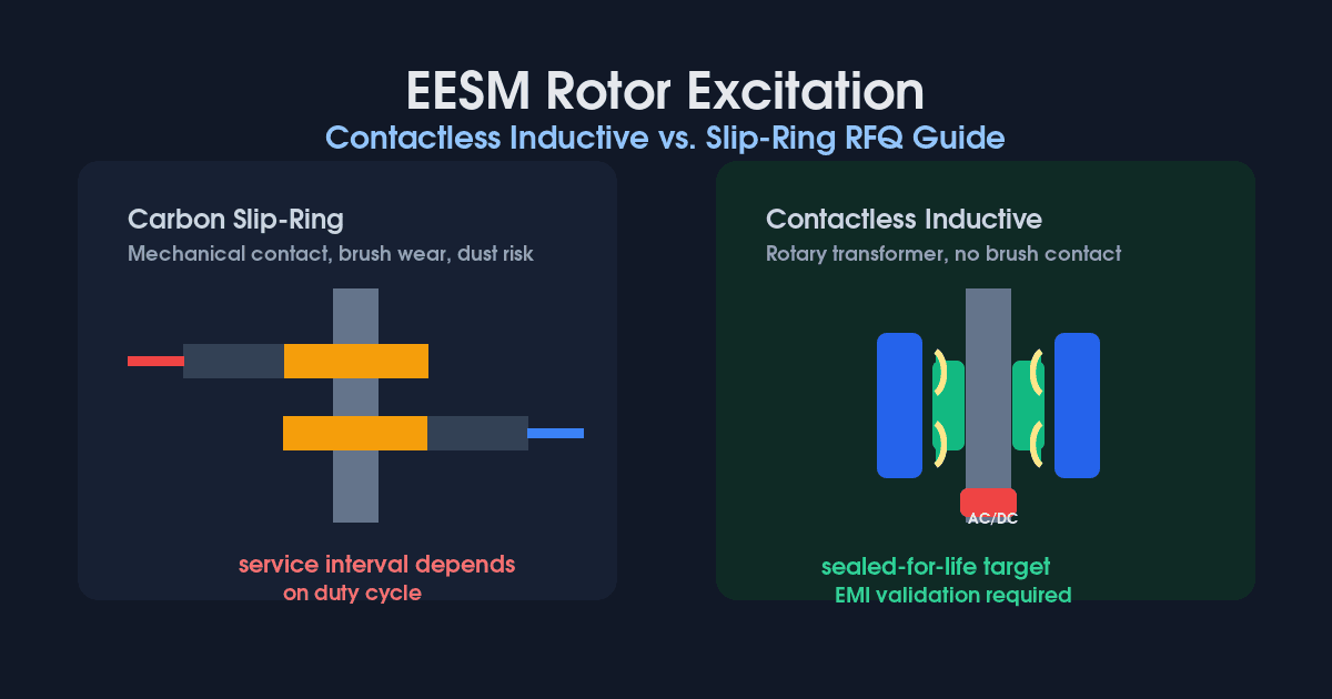
A slip-ring assembly consists of two highly polished conductive metal rings (usually a copper alloy or steel) mounted concentrically on the rotor shaft. Stationary carbon brushes, held under spring tension within a brush holder assembly, press continuously against the spinning rings. The DC excitation current flows from the inverter, through the stationary carbon brushes, across the mechanical sliding contact, into the slip rings, and finally into the rotor windings.
Procurement Advantages
- Low Initial Capital Cost: Slip rings are mechanically straightforward and rely on mature, commoditized manufacturing processes. They do not require exotic semiconductors or complex rotary transformers, making the Bill of Materials (BOM) highly economical.
- Simplicity of Control: The inverter can drive the DC current directly into the rotor with minimal signal conditioning or high-frequency switching requirements. The control loop is highly deterministic.
- Proven Reliability in Controlled Environments: For low-to-medium speed applications (under 12,000 RPM) where periodic maintenance is acceptable, slip rings offer a highly predictable lifespan with decades of historical wear data.
Engineering & Sourcing Drawbacks
- Friction and Mechanical Wear: The physical contact between the carbon brush and the metal ring generates friction. Over time, the brush inherently wears down, making the motor a consumable item requiring periodic servicing—a major disadvantage for sealed EV traction units expected to last 300,000 kilometers.
- Carbon Dust Contamination: As the brushes wear, they generate fine, conductive carbon dust. If this dust migrates into the motor housing or bearings, it can cause catastrophic short circuits or premature bearing failure. Therefore, the slip-ring compartment must be tightly sealed and often requires separate ventilation or dust-capture mechanisms.
- Strict RPM Limitations: Centrifugal forces and aerodynamic lift at very high speeds (15,000+ RPM) can cause the carbon brushes to "bounce" or lose contact with the slip ring, leading to electrical arcing, severe pitting, and instant loss of rotor flux. This places a hard ceiling on the motor's maximum speed, limiting power density.
3. Method 2: Contactless Inductive Excitation (e.g., I2SM)
To overcome the friction and wear limitations of slip rings, Tier-1 automotive suppliers (such as ZF and Mahle) have commercialized Contactless Inductive Excitation systems by 2026. This architecture completely severs the mechanical connection between the stator and the rotor.
How It Works
Instead of sliding contacts, an inductive exciter utilizes the principles of a rotary transformer. A stationary primary coil (transmitter) is mounted inside the motor housing. A rotating secondary coil (receiver) is mounted directly on the rotor shaft, separated from the primary coil by a microscopic air gap (typically less than 1mm).
The inverter sends a high-frequency alternating current (AC) into the primary coil, which magnetically induces an AC voltage in the secondary coil across the air gap. Because the rotor windings require DC power, a miniaturized, high-temperature diode rectifier board is integrated directly onto the spinning rotor shaft to convert the induced AC back into DC before it enters the rotor coils.
Procurement Advantages
- Zero Mechanical Wear (Maintenance-Free): With no physical contact between moving parts, there is zero friction, zero brush wear, and zero carbon dust. The motor can be permanently sealed for life, drastically reducing the Total Cost of Ownership (TCO) and warranty liability for OEMs.
- Ultra-High RPM Capability: Free from the aerodynamic bounce of carbon brushes, inductive EESMs can safely operate at 20,000+ RPM. This allows engineers to design smaller, lighter, higher-revving motors paired with higher reduction gear ratios, achieving greater overall vehicle efficiency and power density.
- Compact Axial Packaging: Modern inductive exciters, such as ZF's I2SM, can be integrated directly into the rotor shaft or placed concentrically within the winding overhangs. This significantly reduces the axial length of the motor compared to bulky slip-ring housings, freeing up critical space in tight EV subframes or industrial chassis.
Engineering & Sourcing Drawbacks
- High Component Cost and Complexity: The BOM is significantly more expensive. It requires precision-machined rotary transformer cores, specialized high-frequency inverters, and ruggedized rotor-mounted diode rectifiers capable of surviving extreme centrifugal G-forces (often requiring carbon-fiber banding or epoxy potting).
- Electromagnetic Interference (EMI): Transmitting high-frequency AC power across an air gap creates a powerful electromagnetic field that can interfere with nearby sensors (like resolvers) and communications networks (CAN bus). Sourcing teams must ensure the supplier has rigorous EMI shielding and validation data.
- Exciter Efficiency Losses: While the motor itself is highly efficient, the inductive power transfer process across the air gap is generally only 90% to 95% efficient. The heat generated by these losses must be carefully managed, often requiring advanced oil-cooling strategies.
4. Architecture Visualization
5. Structured Comparison: Slip-Ring vs. Inductive Excitation
To facilitate rigorous procurement decisions, the following matrix compares the two technologies across the most critical commercial and engineering dimensions:
| Evaluation Dimension | Carbon Slip-Ring Assembly | Contactless Inductive Exciter |
|---|---|---|
| Mechanical Wear | High friction; consumable carbon brushes. | Zero friction; completely solid-state. |
| Maintenance Interval | Brushes must be replaced every 100k - 150k km. | Sealed-for-life; maintenance-free. |
| Max Operating Speed | ~12,000 to 15,000 RPM (Brush bounce risk). | 20,000+ RPM (Limited only by rotor bearings/steel). |
| Axial Packaging Length | Long (Requires separate sealed brush housing). | Ultra-Compact (Integrated inside rotor or overhang). |
| Capital Cost (BOM) | Low (Mature technology, simple materials). | High (Rotary transformers, rotor rectifiers). |
| Inverter Complexity | Low (Direct DC output to rotor). | High (Requires high-frequency AC transmitter). |
| Contamination Risk | Carbon dust generation requires strict sealing/filtration. | None (Ideal for clean-room or sealed-fluid cooling). |
| Cooling Requirements | Standard air or simple jacket cooling. | Often requires direct oil cooling for rotor rectifiers. |
6. Supplier Audit & Procurement Checklist
When drafting RFQs for EESM platforms, purchasing managers cannot treat the motor as a black box. The excitation method dictates the entire lifecycle of the product. Ensure your supplier quality and engineering teams utilize this checklist during the vetting phase:
- Excitation Typology Clarification: Has the supplier explicitly stated whether the EESM uses slip-rings or an inductive exciter in their initial proposal?
- Wear Validation (If Slip-Ring): Has the supplier provided accelerated life testing (ALT) data for the carbon brushes under your specific load profile and ambient temperature? Ask for the guaranteed MTBF (Mean Time Between Failures).
- Dust Mitigation (If Slip-Ring): How does the mechanical design prevent conductive carbon dust from migrating into the stator windings or ball bearings? Is there a dedicated dust trap?
- Rotor G-Force Rating (If Inductive): Because the diode rectifier board is spinning at high speeds, ask for the centrifugal force stress test reports. How is the PCB secured? (Look for high-temp epoxy potting or carbon-fiber retention sleeves).
- EMI Validation (If Inductive): Request Electromagnetic Compatibility (EMC) testing results. Ensure the high-frequency rotary transformer does not induce dangerous noise into the resolver or the vehicle's CAN/LIN bus network.
- System-Level Pricing: Ensure the inverter quote matches the motor. An inductive motor requires a more expensive, specialized dual-output inverter to generate the high-frequency AC field.
If supplier answers conflict on brush life, rotor rectifier retention, EMI margin, or inverter responsibility, pause the award and request an excitation architecture review before separating the motor and inverter purchase orders.
7. Application Boundaries: When to Spec Which Technology
Procurement is about matching capability to reality without over-specifying.
Specify Slip-Ring EESMs For:
- Heavy-Duty Commercial Vehicles: Trucks, buses, and mining equipment where extreme RPMs are unnecessary, space is abundant, and fleet mechanics perform routine preventive maintenance anyway.
- Industrial Automation & Extruders: Stationary industrial applications where the motor operates below 10,000 RPM and initial CAPEX is heavily constrained.
- Cost-Sensitive Tier-2 EVs: Budget-friendly electric platforms where minimizing the inverter and motor BOM cost outweighs the need for a 20,000 RPM redline.
Specify Contactless Inductive EESMs For:
- Premium Passenger EVs & Sports Cars: Applications demanding 20,000+ RPM for maximum power density, ultra-compact drivetrain packaging, and a strict "sealed-for-life" warranty model.
- High-Speed Centrifuges & Spindles: Industrial equipment that requires rapid acceleration and operates in environments where carbon dust contamination is strictly prohibited (e.g., food processing, pharmaceuticals).
- Next-Generation 800V Architectures: Platforms utilizing advanced SiC inverters where system integration allows the high-frequency AC transmitter to be elegantly packaged with the main traction drive.
8. Frequently Asked Questions (FAQ)
Q: Does contactless inductive excitation reduce the overall efficiency of the motor?
A: Marginally. The power transfer across the air gap in an inductive exciter is usually about 90% to 95% efficient, meaning some energy is lost as heat. However, because the motor can safely spin at much higher speeds than a slip-ring motor, engineers can use higher gear reduction ratios, which ultimately increases the system-level efficiency of the vehicle.
Q: Can we upgrade a slip-ring EESM to a contactless EESM later?
A: No. The two architectures require completely different rotor shafts, housing designs, and inverter topologies. The decision must be locked in during the initial platform engineering phase.
Q: If carbon brushes wear out, how difficult is the maintenance?
A: In modern industrial applications, it is relatively straightforward—often a 30-minute job to unbolt an access panel and swap the spring-loaded brushes. However, in tightly packaged passenger EVs, the motor is often buried deep in the subframe, making a brush replacement a highly labor-intensive and costly dealership service.
Q: Why don't we just use Synchronous Reluctance Motors (SynRM) to avoid excitation entirely?
A: SynRM is an excellent, magnet-free solution for partial-load industrial applications like pumps and fans. However, SynRM struggles with high-speed power density and power factor compared to EESM. For EV traction, EESM's ability to actively control its rotor flux (field weakening) makes it far superior for highway cruising.
9. Verifiable Sources and References
To keep the procurement guidance auditable, the architecture examples and excitation constraints above are cross-checked against public vendor releases and technical references. Treat vendor pages as technology examples, then require project-specific validation data from the shortlisted supplier.
- ZF Friedrichshafen AG - I2SM Technology: Official release describing In-Rotor Inductive-Excited Synchronous Motors, brushless inductive power transfer, compact packaging, and rare-earth-free EV drive architecture. View ZF I2SM release
- MAHLE - Contactless Magnet-Free EESM: Official release describing a contactless transmitter for wear-free rotor excitation and supplier-level efficiency claims for magnet-free electric motors. Read the MAHLE release
- Texas Instruments - EESM Excitation Power Stage: Technical brief on electrically excited synchronous machine excitation electronics and inverter integration considerations. Read the TI technical note
Ready to Secure Your Magnet-Free Supply Chain?
Whether your upcoming 2026 platform requires the proven reliability of a slip-ring EESM for heavy industry or the cutting-edge, high-RPM capability of a contactless inductive drive for premium EVs, our advanced manufacturing facilities are equipped to deliver.
We specialize in high-precision rotor winding, high-speed balancing, and rigorous EMI validation for all magnet-free topologies.
Submit your load profile and RFQ to our Engineering Sourcing Team today to receive a comprehensive technical proposal and structural audit.
Author

More Posts
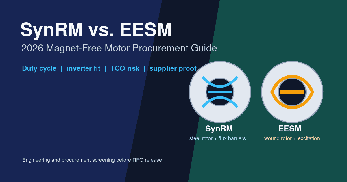
SynRM vs. EESM in 2026: The Ultimate Magnet-Free Motor Procurement Guide
Compare SynRM and EESM magnet-free motor options for 2026 procurement: duty cycles, inverter needs, TCO, supplier checks, and RFQ questions.
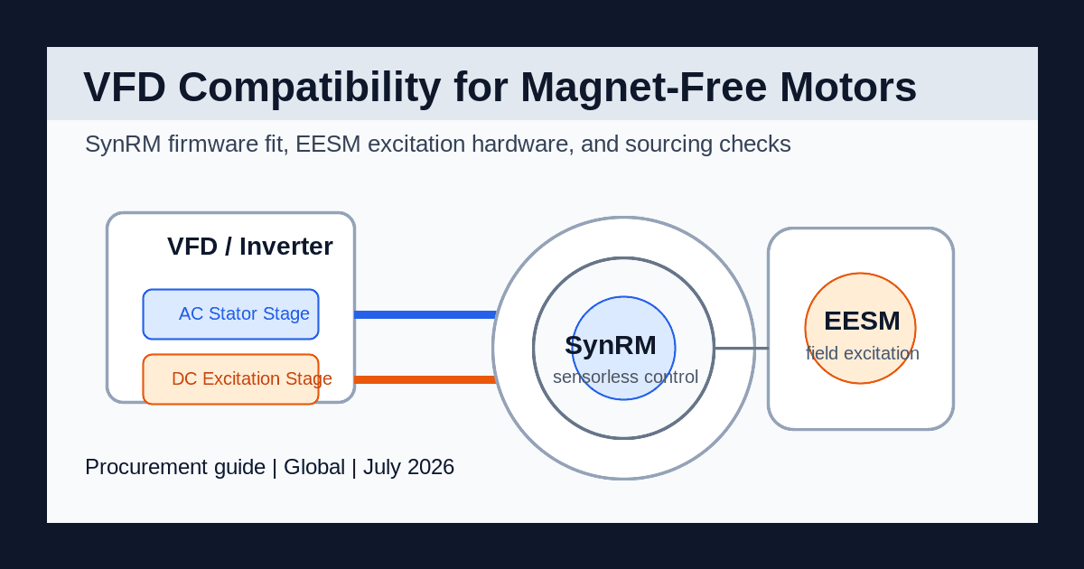
VFD Compatibility with Magnet-Free Motors: SynRM and EESM Sourcing Guide
Compare VFD compatibility for magnet-free motors in 2026: SynRM firmware, EESM excitation hardware, retrofit limits, sourcing checks, and request RFQ review.
IE5 Motor Efficiency Standards Explained: Do You Need Magnets to Comply?
Understand the IE5 Ultra-Premium Efficiency standard. Learn how Synchronous Reluctance Motors (SynRM) achieve IE5 compliance without rare-earth magnets.