

800V SiC Inverter Stress on Magnet-Free Motors: Stator Insulation, PDIV, and Bearing Protection Guide
Specify 800V SiC magnet-free motor insulation, PDIV/RPDIV evidence, and bearing protection. Compare options and use the RFQ checklist before requesting review.
The short answer: An 800V SiC inverter does not, by itself, determine a magnet-free motor's insulation or bearing specification. Qualify the complete motor, inverter and cable arrangement against its terminal waveform, winding construction, environment and bearing-current paths. Neither PEEK wire nor hybrid ceramic bearings are universally mandatory; a Class H thermal rating alone does not establish suitability for fast PWM pulses.
This guide helps global procurement and application engineers compare synchronous reluctance motors (SynRM) and externally excited synchronous motors (EESM) by the evidence needed for approval, rather than by nominal bus voltage or material names.
Published and technically reviewed: October 27, 2026. Region/language: Global / English. Scope: Nominal 700–950V DC-link converter-fed applications, including traction drives and industrial machines. DC-link voltage is distinct from the motor's AC nameplate voltage; specify the actual maximum bus voltage and duty cycle. This screening guide does not replace insulation qualification, application standards or complete-drive validation.
Method and evidence: This is an editorial synthesis of the standards scopes and manufacturer guidance linked below. The decision tables and RFQ questions are our screening framework. Numerical examples are reproducible calculations, not measured motor performance, customer results or evidence of supplier certification.
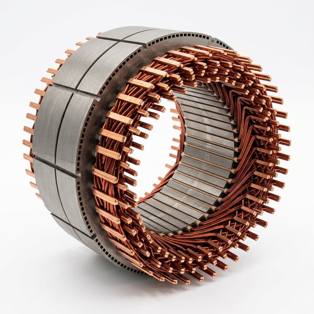
Product illustration only; it does not document qualification of an 800V insulation system.
For related specifications, review our automotive traction motor sourcing guide, brushless excitation system manufacturer guide, hairpin winding engineering overview, EESM vs. IPM procurement comparison, and VFD compatibility evaluation checklist.
Preparing a motor RFQ? Send the inverter waveform, cable layout and duty cycle for an engineering discussion.
1. The Physics of 800V SiC Inverter Stress: Rise Times and Reflected Waves
Fast voltage edges can produce terminal overshoot and uneven voltage distribution within a winding. Switching frequency describes how often pulses occur; rise time describes an individual edge. Specify both, along with gate resistance, modulation and operating conditions. The IEC TS 60034-25:2022 application guide addresses converter-machine interactions and installation considerations.
Rise Times and Slew Rates (dV/dt)
As an illustrative calculation, an 800V step completed in 40 ns has an average slew rate of 800V / 0.04 µs = 20 kV/µs. This is not a universal SiC operating point. Record the voltage interval used for the rise-time measurement, probe bandwidth and measurement location so supplier results are comparable.
Cable Transmission Line Reflection and Voltage Doubling
For a simplified, lossless transmission-line example, assume cable surge impedance of 40 Ω, motor surge impedance of 1,000 Ω and a launched voltage step of 850V:
Reflection coefficient Γ = (Z_motor - Z_cable) / (Z_motor + Z_cable)
                         = (1000 - 40) / (1000 + 40) = 0.923
First-arrival terminal step = 850V × (1 + Γ) ≈ 1,635V
This arithmetic illustrates why a positive reflection can approach twice the launched step. It does not predict an actual terminal peak: motor impedance varies with frequency, and cable length, propagation delay, losses, pulse spacing and terminations matter. An integrated e-axle and a long-cable industrial drive need separate evidence. Confirm worst relevant phase-to-phase and phase-to-ground waveforms at the motor terminals, including regeneration and maximum DC-link conditions.
The High-Frequency Turn-to-Turn Gradient
A winding is a distributed inductive-capacitive network. A fast edge can distribute voltage unevenly, especially near the line end. There is no universal percentage that falls across the first turn. Terminal peak voltage alone does not establish turn-to-turn stress; request a winding model or representative coil/assembly test that accounts for the actual connection layout.
2. The Magnet-Free Motor Dilemma: Copper Fill vs. Dielectric Barrier
Magnet-free describes the rotor's excitation approach, not an insulation class. SynRM develops reluctance torque using stator excitation; EESM supplies rotor field current through a separate excitation system. EESM does not require the stator to supply all magnetizing flux, and neither topology is inherently hotter than every permanent-magnet design.
Hairpin windings can improve geometric copper packing, but they are not required by either topology. Compare copper loss, AC winding loss, cooling and dielectric spacing at the same torque-speed duty. Ask whether a quoted slot-fill factor measures bare copper or insulated conductor area.
Increasing enamel or liner thickness reduces available copper area within a fixed slot. At a fixed conductor length and current, reduced copper cross-section raises resistance and copper loss; it does not automatically require more current for the same torque. Evaluate winding and cooling changes as a complete design rather than assigning a fixed loss penalty to thicker insulation.
Procurement implication: Request a dimensioned slot/insulation stack and a loss/temperature map for the offered winding. A high fill-factor number cannot establish either thermal performance or repetitive impulse capability.
3. Partial Discharge (PD) and Operating-Condition Qualification
Partial discharge is a localized electrical discharge that does not completely bridge the insulation between conductors. It can occur in voids, interfaces or surface regions under sufficient electrical stress and can erode organic insulation. Its onset depends on geometry, waveform, material condition and environment; a simple air-gap breakdown value cannot qualify a finished stator.
PDIV, RPDIV and Insulation-System Type
PDIV is partial discharge inception voltage under a specified test. RPDIV concerns inception under repetitive impulses. A sinusoidal PDIV value and a repetitive-pulse value are not interchangeable. Record pulse polarity, repetition rate, rise time, detection method, noise floor and voltage convention with every reported result.
IEC 60034-18-41:2014 covers qualification and quality-control tests for Type I converter-fed winding insulation systems. Type I systems are intended for operation without partial discharge under their specified service conditions. Type II systems follow a different, discharge-resistant qualification approach. Nominal 800V DC alone does not select the type, impulse-voltage insulation class (IVIC) or test level.
Why Room-Temperature Data May Be Insufficient
Temperature, pressure/altitude, humidity, fluid exposure and ageing can affect inception behavior. There is no universal 30% PDIV derating at 150°C. Ask for data covering the actual winding hot-spot and environmental envelope, rather than applying a fixed correction to a room-temperature coupon result. A thermal Class H designation does not imply continuous operation of every component at 180°C.
For a hypothetical coordination example, if an agreed comparable insulation stress is 1,600V peak and the project selects a 1.25 design factor, the screening target is 2,000V peak. Neither value nor the factor is a universal IEC requirement. Confirm that test and service stresses refer to the same insulation path, waveform and voltage definition. A terminal phase-to-phase peak cannot simply be assigned to a turn pair.
4. Visual Architecture: 800V SiC Electrical Stress Vectors
This conceptual diagram separates differential voltage stress from common-mode bearing stress. Numerical inputs illustrate a scenario; they are not measured thresholds or product ratings. Scroll horizontally on narrow screens to read the full diagram.
5. Stator Insulation Technologies Compared
Use this table to request comparable evidence. These six measures can be combined; they are not standalone voltage ratings. PDIV, IVIC, thermal performance and cost must be established for the assembled insulation system and production process, not inferred from a material name.
| Insulation measure | Potential benefit | Trade-off to compare | Evidence to request | Selection boundary |
|---|---|---|---|---|
| Conventional enamelled conductor | Established winding process | Repetitive-pulse capability depends on the system | Formed-wire and representative winding qualification | Consider only if the complete system meets the actual stress envelope |
| Corona-resistant (CR) enamel | May improve resistance to discharge erosion | Erosion resistance does not establish PD-free operation | Material data plus assembly PD/endurance evidence | Do not treat a CR label as Type I approval |
| Extruded PEEK conductor coating | Alternative dielectric and chemical protection | Coating thickness, bend damage, joining and cost | Post-forming inspection, fluid ageing and winding qualification | Compare with qualified enamel systems; not mandatory for every 800V drive |
| Slot liners and phase barriers | Separate conductors from core and other phases | Reduce slot space; edges and joints remain critical | Actual thickness, overlap, edge geometry and assembly tests | A sheet breakdown rating is not a motor impulse rating |
| VPI or trickle impregnation | Improve resin coverage and winding support | Distinct processes; voids and cure depend on geometry | Process settings, cut sections or validated inspection, PD correlation | Neither process name guarantees a void-free stator |
| Full encapsulation/potting | May improve heat paths and environmental protection | Mass, repairability, expansion stress and material compatibility | Thermal cycling, fluid compatibility and PD/endurance data | Validate resin, conductor and liner together; no automatic IVIC upgrade |
How to Compare Supplier Quotes
Hold conductor geometry, duty, cooling, waveform and validation scope constant. Compare tooling, process yield, qualification work and repair implications separately from material price. There is no defensible universal BOM multiplier or current-density uplift for PEEK or potting.
A thin coupon with high dielectric strength may still fail after conductor forming, welding, impregnation or thermal cycling. Request evidence from the offered production route, with any difference between test sample and final stator explicitly documented.
6. Bearing Currents and Electrical Discharge Machining (EDM) Mitigation
With phase voltages referred to the same reference, common-mode voltage is:
V_cm = (V_a + V_b + V_c) / 3Its instantaneous value depends on inverter switching states and modulation; it need not always be nonzero. Capacitive coupling can raise shaft voltage. Lubricant-film discharge can cause electrical erosion, while circulating and shaft-grounding currents introduce other paths. SKF's electrical-erosion guide explains these mechanisms and why the complete drive must be considered.
Bearing Protection Topologies Comparison
| Protection option | Intended role | Limitation / verification question |
|---|---|---|
| Steel bearings with verified bonding/cabling | Retain a conventional bearing arrangement where exposure is acceptable | Require application evidence; nominal bus voltage alone does not prohibit steel bearings |
| Shaft grounding ring or brush | Provide a controlled path around the bearing | Confirm contact reliability, contamination exposure, wear and maintenance requirements |
| Ceramic-coated bearing ring | Increase electrical impedance through one bearing path | Check high-frequency behavior; DC resistance alone is insufficient |
| Hybrid ceramic bearing | Insulate rolling contacts using ceramic rolling elements | Validate bearing arrangement, seals, loads, lubrication and remaining current paths |
SKF's hybrid-bearing guidance describes electrical insulation and application-dependent mechanical benefits; it also notes that some arrangements need both bearings considered. No option establishes a universal speed limit, efficiency gain or lifetime for an 800V motor. Qualification should include the connected load, where current can find an alternative path.
For the RFQ, agree how shaft voltage and discharge/current activity will be measured across the duty envelope, and what constitutes acceptance. A single low shaft-voltage reading or an insulation-resistance value is not a lifetime guarantee.
7. RFQ & Supplier Audit Checklist: 800V Magnet-Free Stator & Bearing
Use this as a document-request checklist. The buyer, drive integrator and motor supplier must agree application-specific acceptance criteria before qualification or production testing.
- Voltage envelope: Record nominal and maximum DC-link voltage, regeneration conditions, switching settings, cable length/type and filter arrangement.
- Terminal waveforms: Supply measured or validated worst-case phase-to-phase and phase-to-ground peaks, rise times and ringing, with measurement uncertainty and probe details.
- Insulation-system qualification: Identify the applicable standard edition/amendments, system type and IVIC where applicable. Request the report and its covered service envelope rather than prescribing a universal Class C rating.
- PD evidence: Request the relevant PDIV/RPDIV method, waveform and detection sensitivity, with temperature, altitude/pressure, humidity and ageing conditions matched to service. Compare like insulation paths and agree design margins.
- Winding construction: Record enamel/coating, conductor dimensions, liners, phase barriers, lead routing and formed/welded regions. Require evidence for the assembled stack, not just raw materials.
- Impregnation or potting quality: Record the actual process and inspection method, sampling plan and acceptance criteria. Agree coverage/void criteria for this design instead of imposing an unsupported universal void fraction.
- Type tests vs. production tests: Separate design endurance qualification from agreed routine surge/withstand/PD checks. Define pulse level, rise time and pass/fail criteria; do not adopt a generic 2,500V/50 ns production pulse from this article.
- Bearing-current control: Identify grounding, insulated/hybrid bearings and load-side paths as a system. Request duty-envelope measurements and maintenance assumptions, rather than a universal shaft-voltage threshold.
- Change control: Require review of changes to inverter settings, cable, filters, wire, liner, resin, cooling fluid or bearing arrangement that could invalidate the qualification evidence.
If the qualification envelope or bearing-current paths remain unclear, bring the supplier report and open questions to an engineering RFQ discussion before approving the design.
8. Application Boundaries: Matching Insulation to Duty Cycle
Select the least complex arrangement that meets documented electrical, thermal, mechanical and environmental requirements. These are screening distinctions, not automatic material approvals:
- Integrated traction drives: Short connections do not remove the need to characterize busbar/cable parasitics and local winding stress. Include maximum DC link, regeneration, oil exposure, winding temperature and rotor excitation where applicable.
- Long-cable industrial drives: Check cable propagation effects, grounding, the connected machine and any output filter. Rated AC supply voltage and DC-link voltage are different quantities.
- High-speed or inaccessible equipment: Review bearing load/speed ratings, lubrication, grounding-contact maintenance and repair access. A high rotational speed alone does not mandate a particular ceramic-bearing or wire-coating technology.
When Enamelled Wire or Output Filtering May Be Suitable
A qualified enamel-based insulation system may meet the actual stress envelope. A correctly selected dV/dt or sine-wave filter can reduce relevant stresses, but its effect depends on topology, cable, load and grounding. Agree measurements for differential and common-mode behavior separately; filtering does not automatically eliminate reflections or bearing currents. Compare mass, loss and cost using supplier data for the actual design.
When to Evaluate PEEK, Potting or Hybrid Bearings
Evaluate these options when the existing design cannot meet the specified waveform, temperature, fluid or bearing-current conditions, or when maintenance constraints justify them. Check manufacturing damage, ageing and the complete assembly. Neither a material upgrade nor a nominal 800V label establishes zero PD, zero bearing damage or a guaranteed service life.
9. Frequently Asked Questions (FAQ)
Q1: Do magnet-free motors always run hotter than permanent-magnet motors?
No. SynRM needs stator magnetizing current, while EESM has a separately excited rotor. Loss and temperature maps depend on electromagnetic design, control, cooling and duty. Compare equivalent operating points; do not assume a fixed current or temperature penalty from the absence of magnets.
Q2: Can a dV/dt filter solve the 800V SiC reflection problem?
It can reduce voltage edge stress when correctly selected for the drive and cable. Verify terminal peaks, rise times and thermal effects in the intended arrangement. Differential-mode filtering and common-mode current mitigation address different aspects of the system; one does not automatically qualify the other.
Q3: Is hairpin wire inherently safer than round wire under SiC stress?
No. Controlled placement can help model local voltage stress, but electrically distant conductors can still be physically adjacent. Hairpin bends, welds, crossings and phase boundaries need qualification. Round-wire and hairpin systems should both be assessed using representative construction and waveforms.
Q4: Does direct stator oil cooling help insulation reliability?
Cooling can reduce thermal stress, but the complete wire/liner/resin/fluid combination needs compatibility and ageing evidence. Include moisture, contamination and pressure conditions in the qualification plan. A cooling method alone cannot establish PD inception voltage or service life.
Q5: Do hybrid ceramic bearings guarantee no bearing-current damage?
They provide insulation at rolling contacts, but the complete current path and bearing assembly still require review. Other bearings, seals, shaft couplings and connected equipment can affect the result. Ask for application-specific evidence rather than a universal speed, friction-saving or life multiplier.
10. Verifiable Sources and Engineering Standards
Sources checked: October 27, 2026. The IEC links establish publication identity and scope; the full standards and applicable amendments are needed to define qualification requirements. The older SKF articles explain electrical-current mechanisms, not certification of modern 800V SiC traction hardware. The selection tables and numerical examples above are editorial screening aids, not limits quoted from these publications.
- IEC 60034-18-41:2014 — Type I converter-fed insulation qualification and quality-control tests. Publisher scope for stator/rotor winding insulation assessment; confirm the edition and applicable amendments in the project test plan.
- IEC TS 60034-25:2022 — AC electrical machines used in power drive systems: application guide. Publisher scope for converter-machine interaction, installation and shaft-current considerations.
- SKF Evolution — Prevention of electric erosion in bearings, September 15, 2001. Background on current paths, lubricant-film discharge and the high-frequency behavior of insulated bearings.
- SKF Evolution — Hybrid bearings for electrical machinery, September 16, 2001. Background on ceramic rolling elements, bearing arrangements and application-dependent lubrication/mechanical considerations.
Ready to Review Your 800V Magnet-Free Motor RFQ?
Share your inverter specification, cable layout, winding temperature range and available qualification reports with our team. Use the checklist above to identify missing evidence and agree the next engineering questions. Confirm the offered manufacturing process, test capability and qualification scope in the supplier proposal before placing an order.
Author

More Posts
EESM vs. IPM Motors in 2026: Cost, Supply Chain, and Procurement Guide
Compare EESM vs. IPM motors for magnet-free motor sourcing in 2026: rare-earth risk, copper cost, inverter needs, efficiency, and RFQ checks.

EU CRMA 2026: Why Magnet-Free Motors Are the Safest Compliance Strategy
How the EU Critical Raw Materials Act (CRMA) affects 2026 motor procurement. Compare NdFeB tracking overhead against magnet-free EESM and SynRM alternatives.
How to Audit a B2B Motor Manufacturer: Evaluating OEM Capabilities
A buyer's guide to auditing motor manufacturers. Learn how to evaluate testing labs, dyno capacity, and quality control in magnet-free motor production.