Home / Learn / Brushless Excitation System
EESM Screening Tool & GuideReviewed

Brushless Excitation System Calculator

Calculate rotor loads and diode losses, then compare excitation architectures and evidence. EESM screening only; engineering verification required.

Rotor load & diode loss calculator

Editable example, not recommended ratings. Passive diode bridge; results update instantly. View results ↓

Screening inputs

1,000–30,000 rpm; numerical screening range, not a qualified speed limit.

20–120 mm from the shaft axis to the component centroid.

0.5–25 kW continuous DC field power; not motor shaft power.

5–100 A at the same operating point as field power.

0.2–2.2 V; use the device curve at operating current and temperature.

Optional thermal scenario (3 inputs)

0.01–20 K/W; hottest-junction rise divided by total bridge power. Use measured assembly data.

−40–200°C; boundary used by the entered thermal resistance.

50–250°C; enter the actual device limit and apply your derating policy separately.

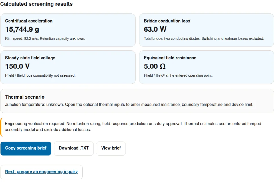
Calculated screening results

Calculator loading. Enable JavaScript to edit.

Centrifugal acceleration

15,744.9 g

Rim speed: 92.2 m/s. Retention capacity unknown.

Bridge conduction loss

63.0 W

Total bridge, two conducting diodes. Switching and leakage losses excluded.

Steady-state field voltage

150.0 V

Pfield / Ifield; bus compatibility not assessed.

Equivalent field resistance

5.00 Ω

Pfield / Ifield² at the entered operating point.

Thermal scenario

Junction temperature: unknown. Open the optional thermal inputs to enter measured resistance, boundary temperature and device limit.

Engineering verification required. No retention rating, field-response prediction or safety approval. Thermal estimates use an entered lumped assembly model and exclude additional losses.

Next: prepare an engineering inquiry

Key Engineering & Architectural Decisions

Public evidence supports these decisions within the limits stated below. Engineering recommendations are screening guidance, with unknowns identified rather than inferred from product announcements.

FINDING 196% peak at 7 kW; prototype

A measured IPT prototype is a useful benchmark

ORNL reports laboratory operation up to 20,000 rpm and 25 A, with 96% maximum efficiency at 7 kW. Ask for the candidate design’s efficiency map, cooling conditions and durability evidence before transferring that benchmark.

Evidence & primary citations: Oak Ridge National Laboratory / IEEE.
FINDING 2Whole-drive comparison

Separate drivetrain gains from excitation gains

BMW’s Gen6 figures cover the wider drive concept. They cannot be used as a brushless-exciter efficiency or cost improvement in a business case.

Evidence & primary citations: BMW Group.

FINDING 3Axle kW ≠ field kW

Distinguish axle output from field power

The iBEE announcement targets 220–350 kW peak axle output. Size the exciter from the rotor field voltage, current and duty cycle, rather than a fraction inferred from that axle rating.

Evidence & primary citations: Valeo / MAHLE.

FINDING 4Vendor-specific baseline

Treat compactness as a packaging study

ZF’s in-shaft approach shows why contactless transfer can help packaging. Check shaft bore, bearing span, resolver clearance and service access before claiming a length saving.

Evidence & primary citations: ZF.

FINDING 5Assembly validation required

Acceleration is a load input, not a safety rating

The calculator supplies kinematics. Retention also depends on mass, attachment geometry, materials, temperature and fatigue. Balancing alone cannot certify an assembly against release.

Evidence & primary citations: ISO.

FINDING 6Response: design-specific

Specify response and shutdown acceptance explicitly

Field inductance, available voltage and discharge path determine the transient. Agree the measurement definition and fault cases; do not derive a fixed response time from an architecture name.

Evidence & primary citations: IEC.

Mathematical Methodology & Physical Equations

The tool applies kinematics and steady-state electrical identities at one operating point. The input bounds are numerical screening limits, not validated product ratings. All required inputs are editable examples.

Radial acceleration
ω = 2πN / 60; a/g = ω²r / 9.80665. N in rpm, r in metres. Rim speed = ωr. Retention capacity is not calculated.
Field voltage and resistance
Vfield = 1000 × Pfield(kW) / I; Rfield = Vfield / I. Both use the same continuous operating point and exclude transfer losses.
Passive bridge conduction
Pbridge ≈ 2 × VF × I, assuming two conducting diodes and approximately continuous DC current. Switching, leakage, magnetic and converter losses are excluded. Active rectifiers need a different model.
Optional lumped thermal scenario
Tj ≈ Tboundary + Pbridge × Rθ. Enter an assembly resistance based on total bridge power and the hottest junction, plus a boundary temperature and actual device limit. This is a conduction-only steady-state scenario.
Unknown outputs
Mechanical safety, full transfer efficiency and field response cannot be established from these inputs. Request attachment analysis, complete loss maps, field inductance, voltage ceiling and fault tests.
Contactless field power path: Stationary inverter + primary coil → Air gap → rotating coil + rectifier → DC field winding on the rotor1. Stationary inverter + primary coil2. Air gap → rotating coil + rectifier3. DC field winding on the rotor
Contactless field power path. Conceptual IPT path. Carrier frequency, gap, device ratings and field response must be designed and verified.
Calculated radial acceleration at 55 mm radius. 10,000 rpm: 6,150 g; 20,000 rpm: 24,601 g; 30,000 rpm: 55,353 g. No allowable limit is shown.0k g20k g40k g60k g0k10k20k30kRotational speed (rpm)
Calculated from a/g = (2πN/60)² × 0.055 / 9.80665. Fixed 55 mm example radius; doubling speed quadruples acceleration. This is not a strength curve.

1. Choose the excitation architecture

A brushless excitation system supplies the rotating field without sliding electrical contacts. This page focuses on EESM motor screening; industrial generator excitation also needs its own regulator and grid-duty assessment. The comparisons below are engineering screening guidance, not product ratings.

Table 1: Multi-dimensional comparison matrix (horizontal scroll on mobile)

ArchitectureDecision valueWhat must be checked
Slip rings and brushesDirect electrical access to the field; useful comparison baselineWear, dust containment, service interval and field control
Synchronous AC exciter + rotating rectifierEstablished contactless arrangement for synchronous machinesStarting/low-speed supply, magnetic design and rotor packaging
High-frequency rotary transformer (IPT)Carrier excitation can be independent of shaft speedResonant tuning, leakage, rotating electronics and EMI
Capacitive couplingAlternative contactless research routeVoltage stress and dielectric/gap sensitivity; no readiness ranking established here
Architectural Boundary / Sizing Constraint: No universal speed, maintenance interval or flux-response range follows from topology alone. An AC exciter may need a special starting arrangement.
Architecture screening: Define starting and duty needs → Compare transfer paths → Request operating maps1. Define starting and duty needs2. Compare transfer paths3. Request operating maps
Architecture screening. Sequential engineering decision logic.

Evidence & primary citations: Oak Ridge National Laboratory / IEEE; IEC.

2. Specify the rotary transformer interface

A resonant network can compensate reactive impedance, but tuning must cover the complete operating range. LCC and series compensation are candidate circuits rather than guarantees of gap-independent power.

Table 2: Multi-dimensional comparison matrix (horizontal scroll on mobile)

ParameterWhy it mattersEvidence to request
Gap and runoutChange coupling and leakage inductanceTolerance stack and operating gap sweep
Carrier frequencyAffects magnetic, switching and EMI lossesMeasured loss and emission maps
Resonant componentsTolerance and temperature shift tuningWorst-case circuit analysis and bench sweep
Zero speedStartup requires a viable field supplyStationary transfer and startup demonstration
Architectural Boundary / Sizing Constraint: The calculator does not solve magnetic coupling, turns ratio, resonance, efficiency or startup.
Coupling validation: Define gap tolerance → Sweep load and tuning → Measure hot performance1. Define gap tolerance2. Sweep load and tuning3. Measure hot performance
Coupling validation. Sequential engineering decision logic.

Evidence & primary citations: Oak Ridge National Laboratory / IEEE.

3. Calculate conduction loss without hiding assumptions

The tool assumes a passive full bridge carrying approximately continuous DC current. Two devices conduct in series, so total bridge conduction loss is approximately 2 × VF × I. VF must represent the actual operating current and temperature.

Table 3: Multi-dimensional comparison matrix (horizontal scroll on mobile)

Model elementIncluded hereMissing information
Diode conductionTotal bridge loss at one operating pointCurrent waveform and device curve across temperature
Switching and reverse leakageExcludedFrequency, reverse voltage and device data
Active MOSFET rectificationOutside this diode modelRDS(on), gate supply, timing and commutation model
Device stressNo voltage rating selectedTransient peak, reverse rating and derating policy
Architectural Boundary / Sizing Constraint: Total bridge loss is not one diode’s loss. A lumped assembly thermal resistance must use the same total-power basis.
Rectifier selection: Obtain device curves → Calculate all loss terms → Validate the assembly1. Obtain device curves2. Calculate all loss terms3. Validate the assembly
Rectifier selection. Sequential engineering decision logic.

4. Turn centrifugal acceleration into a validation plan

Acceleration scales with speed squared and linearly with mounting radius. For each component, radial load is mass × acceleration. A material name alone cannot provide an allowable g rating.

Table 4: Multi-dimensional comparison matrix (horizontal scroll on mobile)

CheckRequired inputDecision
Radial loadComponent mass, radius and speedUse calculated acceleration in attachment analysis
Retention strengthGeometry, interference, material curves and temperatureCalculate assembly stresses and fatigue
BalanceRotor behaviour and residual unbalance toleranceAgree rigid/flexible rotor procedure
Combined testsHot duty, overspeed case and containment planSet acceptance criteria before testing
Architectural Boundary / Sizing Constraint: No pass/fail mechanical claim is made by this tool. A lower calculated g value still requires mechanical review.
Mechanical release: Calculate component loads → Review attachment and fatigue → Agree contained testing1. Calculate component loads2. Review attachment and fatigue3. Agree contained testing
Mechanical release. Sequential engineering decision logic.

Evidence & primary citations: ISO.

5. Assess cooling with measured thermal inputs

Oil flow, dry conduction and spray cooling need assembly-specific evidence. Enter a thermal resistance only if it represents the hottest junction temperature rise divided by total bridge power for the chosen installation.

Table 5: Multi-dimensional comparison matrix (horizontal scroll on mobile)

Cooling routePotential benefitTrade-off and evidence
Shaft conduction in dry cavityAvoids direct fluid exposureContact and bearing paths may constrain heat flow; measure thermal impedance
Hollow-shaft fluid coolingCan bring coolant near the rectifierValidate flow delivery, sealing, drag and material compatibility
External jet or splashMay share existing lubricationWetting depends on speed and geometry; test coverage
Unknown thermal resistanceNo justified junction predictionLeave optional tool fields blank and request a thermal test
Architectural Boundary / Sizing Constraint: Tj ≈ Tcoolant + Pbridge × Rθ is a steady-state scenario. Omitted losses, transient heating and nonuniform device dissipation may change the hottest junction.
Thermal evidence: Measure total loss → Measure hottest junction path → Review duty and margin1. Measure total loss2. Measure hottest junction path3. Review duty and margin
Thermal evidence. Sequential engineering decision logic.
Review results and download your screening brief

6. Define field response and fault shutdown

Field response requires an electrical model and a test definition. For a linear constant-RL winding driven by a voltage step from zero, τ = L/R and the 10–90% current rise is approximately 2.20τ. That simplified result does not include saturation or control limits.

Table 6: Multi-dimensional comparison matrix (horizontal scroll on mobile)

QuestionNeeded evidenceMinimum next step
Field rise timeInductance, hot resistance, ceiling voltage and control limitsAgree initial/final current and timing definition
Field decayStored energy (½LI²) and available discharge pathSimulate decay voltage and current
Inverter or exciter faultCoordinated machine/inverter fault analysisReview rotor energy and diode reverse stress
Clamp or dump circuitEnergy rating, repetition and temperatureSelect protection after transient analysis
Architectural Boundary / Sizing Constraint: An MOV is one possible protection component; neither a fixed clamp voltage nor a sub-50 ms shutdown is established here.
Shutdown coordination: Define fault and energy → Model discharge path → Verify voltage and decay1. Define fault and energy2. Model discharge path3. Verify voltage and decay
Shutdown coordination. Sequential engineering decision logic.

Evidence & primary citations: IEC.

7. Check insulation against actual waveforms

The traction DC bus and rotor DC field are different electrical nodes. Field power divided by field current gives a steady-state field voltage; it does not establish isolation voltage, transient withstand or converter turns ratio.

Table 7: Multi-dimensional comparison matrix (horizontal scroll on mobile)

InterfaceStress to characterizeEvidence needed
Primary converterDC bus variation and switching transientsInput range and surge envelope
Rotary air gapIsolation, contamination and runoutGeometry and dielectric assessment
Rotor rectifier and windingInduced peaks and common-mode couplingMeasured waveforms and device/insulation limits
Winding insulation systemConverter pulse waveform and insulation typeApplicability review and qualification plan
Architectural Boundary / Sizing Constraint: IEC 60034-18-41 addresses Type I insulation within its scope. It is not an automatic certification for every high-frequency exciter.
Insulation review: Map electrical nodes → Measure worst-case pulses → Select qualification tests1. Map electrical nodes2. Measure worst-case pulses3. Select qualification tests
Insulation review. Sequential engineering decision logic.

Evidence & primary citations: IEC.

8. Build an auditable acceptance checklist

The following is a proposed review plan. Test methods and thresholds must be agreed with the machine owner and relevant specialists; this page does not assert compliance or testing capability.

Table 8: Multi-dimensional comparison matrix (horizontal scroll on mobile)

Evidence packageAcceptance questionDo not substitute
Electrical and thermal mapAre power, efficiency and temperature measured over duty?A single peak efficiency number
Mechanical dossierAre hot attachment loads, balance and rotor behaviour covered?A material-wide g rating
Insulation evidenceDo representative tests reflect the actual pulse stress?A generic 800V label
Fault and endurance recordsDo measured decay, cycling and environment meet agreed limits?A component datasheet alone
Architectural Boundary / Sizing Constraint: Public standards abstracts identify scope. Review the licensed editions, amendments and contractual requirements before planning qualification.
Acceptance evidence: Agree requirements → Review representative tests → Close evidence gaps1. Agree requirements2. Review representative tests3. Close evidence gaps
Acceptance evidence. Sequential engineering decision logic.

Evidence & primary citations: ISO; IEC; IEC.

9. Read public benchmarks on their own terms

Publication dates and access date are listed in the evidence directory. These examples demonstrate different kinds of evidence; they are not a supplier ranking or comparable efficiency dataset.

Table 9: Multi-dimensional comparison matrix (horizontal scroll on mobile)

Public exampleKnownUnknown / not transferable
ORNL, APEC 2026Prototype test limits and one maximum-efficiency pointLifetime and full production operating map
BMW, February 2025800V drive-generation comparisonExcitation-only contribution to those gains
Valeo–MAHLE, October 2024iBEE joint-development targetCurrent nomination/delivery status from this announcement
ZF, September 2023Vendor in-shaft integration and length comparisonPackaging saving in a different machine
Architectural Boundary / Sizing Constraint: Use each source for the claim it actually supports. Request dated production status and design-specific data directly when sourcing.
Benchmark discipline: Identify comparison scope → Separate facts and unknowns → Ask for matching evidence1. Identify comparison scope2. Separate facts and unknowns3. Ask for matching evidence
Benchmark discipline. Sequential engineering decision logic.

Evidence & primary citations: Oak Ridge National Laboratory / IEEE; BMW Group; Valeo / MAHLE; ZF.

Packaging Envelopes: In-Shaft Coaxial vs. Overhung

Integrating a contactless brushless exciter into an existing powertrain architecture requires careful spatial budgeting. The packaging target depends on the machine. Compare in-shaft and overhung layouts against the actual shaft, bearing and cooling envelope before claiming a length saving.

Packaging review: Reserve shaft / end-bell space → Check bearings, resolver and flow → Compare complete motor envelopes1. Reserve shaft / end-bell space2. Check bearings, resolver and flow3. Compare complete motor envelopes
Packaging review. In-shaft integration trades axial space against shaft bore, assembly access and thermal paths. No universal length saving is assumed.

System Risks, Failure Modes & Mitigation Strategies

Transitioning from mechanical slip rings to solid-state brushless excitation exchanges wear friction risks for thermal, mechanical hoop stress, and electromagnetic interference challenges.

Centrifugal Diode Shear & Delamination

Use component masses and calculated acceleration to derive radial loads. Review attachment stresses, thermal expansion, fatigue and containment before agreeing hot spin tests. Lower radius may reduce load, but does not certify a material or joint.

Thermal Runaway in Dry Sealed Cavities

Conduction loss is only part of the heat budget. Measure the hottest junction thermal path over the duty cycle. Compare dry conduction and fluid cooling with flow, sealing, lubricant compatibility and pump-power effects included.

High-Frequency EMI Coupling to Resolvers

Carrier switching can disturb position sensing. Measure common-mode paths and resolver signals before choosing shielding, filtering or grounding; shielding itself can create eddy-current heating.

Inverter 3-Phase Short Circuit Inductive Spikes

Review stored field energy and fault current paths with the inverter owner. Size and test the discharge circuit against actual voltage, energy and repetition limits; a universal clamp voltage is not justified.

Cost and application mismatch

Brushless transfer adds converter electronics, rotating packaging and validation cost. Compare total service cost and duty requirements against a brush/slip-ring baseline. For low-speed industrial duty, assess a conventional AC exciter before assuming a traction IPT design fits.

Worked Engineering Scenarios & Sizing Case Studies

Review detailed engineering trade-offs, sizing calculations, and sensitivity checks. These are illustrative calculations, not production case histories or validated component selections.

Example A: nominal field sizing

Application Premise: Illustrative inputs: 16,000 rpm, 55 mm radius, 4.5 kW field power, 30 A and VF = 1.05 V.

Engineering Process: The model gives approximately 15,744.9 g, 150.0 V field voltage, 5.00 Ω hot equivalent resistance and 63.0 W total bridge conduction loss.

Next decision: Export the loads for review. Mechanical capacity, switching loss, junction temperature and response remain unverified.

Example B: reduce mounting radius

Application Premise: Keep Example A’s speed and electrical values; move the diode centroid from 55 mm to 30 mm.

Engineering Process: Acceleration falls to approximately 8,588.1 g because radius enters linearly. Electrical voltage and bridge conduction loss stay unchanged.

Next decision: Compare attachment loads and packaging. This reduction alone does not approve the retention design.

Example C: thermal sensitivity

Application Premise: Use 63 W conduction loss, 75°C coolant and an assumed assembly Rθ of 0.75 K/W, then compare 1.5 K/W.

Engineering Process: The simplified steady-state temperatures are 122.3°C and 169.5°C. With an entered 150°C limit, the second scenario exceeds it even before omitted losses.

Next decision: These Rθ values are illustrative, not cooling-method ratings. Measure the installed path and revise the complete loss budget.
Brushless excitation system calculator example showing 15,744.9 g rotor acceleration, 63 W bridge conduction loss and 150 V field voltage
Reproduced software run, 2026-10-29: reset the example to 16,000 rpm, 55 mm, 4.5 kW, 30 A and 1.05 V per diode. The conduction-only results are calculated, not measured hardware performance or customer proof. Optional thermal data remain unknown.

Sources, Empirical References & Evidence Directory

Sources checked on . Reported measurements, vendor disclosures and public standard scopes are distinguished below. Calculator examples and engineering review steps are our stated derivations, not measured product performance.

Published by Magnet-Free Motor. First recorded in this repository: . Review method: check primary publication scopes, reproduce the worked calculations and verify the calculator exports. Review again by , or when cited specifications change. Contact the publisher to report a correction.

Oak Ridge National Laboratory / IEEE2026 (conference: March 22–26)

Rotary Transformer for Wound Rotor Synchronous Motors (APEC 2026)

Supports: Public abstract: prototype testing up to 20,000 rpm and 25 A; maximum efficiency of 96% at 7 kW. DOI: 10.1109/APEC51134.2026.11517114.

Scope Limitation: These are reported test limits and a peak operating point, not a complete efficiency map or qualification for another design. Public abstract reviewed; full paper not independently reproduced.

BMW Group2025-02-21

Charge faster, drive further: Gen6 electric drive with 800V technology

Supports: BMW describes an 800V generation combining EESM and ASM options. Its 40% loss, 20% cost and 10% weight reductions compare the drive concept with Gen5 xDrive.

Scope Limitation: Corporate comparison across multiple changes; it does not isolate brushless excitation benefits or disclose a transferable rectifier design.

Valeo / MAHLE2024-10-14

Joint development of iBEE (Inner Brushless Electrical Excitation)

Supports: Development announcement for a 220–350 kW peak-power electric axle using MAHLE contactless transmitter technology with Valeo motor and inverter expertise.

Scope Limitation: Peak axle power is not rotor excitation power. This dated announcement does not establish current delivery status, service life, thermal resistance or field response.

ZF2023-09-01

ZF makes magnet-free electric motor uniquely compact and competitive

Supports: ZF describes an inductive exciter inside the rotor shaft and up to 90 mm less axial installation space relative to common separately excited synchronous motors.

Scope Limitation: Vendor-specific packaging comparison; it is not a universal 90 mm saving or proof of identical packaging for every permanent-magnet motor.

ISO2016-11 (amendment: 2022)

ISO 21940-11:2016 — Rotor balancing, rigid behaviour

Supports: Public scope covers balancing procedures and unbalance tolerances for rigid rotors; flexible rotor behaviour is outside this part.

Scope Limitation: Scope review only. Select the balance grade and applicable amendments with the machine owner; balancing is not retention strength or overspeed certification.

IEC2019-06-25 (2020 corrigendum included)

IEC 60034-18-41:2014+AMD1:2019 CSV — Type I insulation

Supports: Qualification and quality-control scope for converter-fed stator/rotor winding insulation systems of Type I.

Scope Limitation: Applicability and test levels require review of the actual waveforms, insulation type and assembly. The public scope is not a full compliance assessment.

Frequently Asked Technical Questions

Architecture

What is a brushless excitation system?

It transfers power to a rotating field without sliding brush contacts. Common approaches include an AC exciter with rotating rectification and an inductive rotary transformer.

Does this page cover generator AVR selection?

The tool screens motor rotor loads. Generator voltage regulation, grid transients and exciter sizing require a machine-specific study beyond this model.

Does an EESM always have brushless excitation?

No. EESM describes the electrically excited machine; its rotor can be supplied through contacts or a contactless transfer arrangement.

Can the selected system excite the rotor at standstill?

Ask for a zero-speed demonstration. A high-frequency rotary transformer can operate independently of rotation; an AC exciter needs an appropriate starting supply or arrangement.

Calculator and limits

Are the default values recommended ratings?

No. They are an editable worked example. Replace them with the candidate machine’s continuous operating values.

Why is there no safe retention label?

Acceleration is only a load input. Strength and fatigue depend on the entire attachment, component masses and hot material properties.

Is the loss output for one diode or the whole bridge?

It is total bridge conduction loss, assuming two conducting devices and approximately continuous field current. Switching, leakage and other losses are excluded.

Can I use the diode model for active rectification?

No. An active bridge needs channel resistance, switching timing, commutation and gate-supply losses; an arbitrary multiplier is not a valid substitute.

Why is junction temperature initially unknown?

No verified assembly thermal path or device limit was supplied. Add all three optional inputs for a scenario, or request installed thermal measurements.

Does field voltage have to equal the traction bus?

No. The transfer and converter design establish the relationship. The tool derives only steady-state field voltage from entered field power and current.

Validation

Can I select a material by a generic g capability?

No. Analyze geometry, mass, attachments, interference, temperature and fatigue, then define representative mechanical tests.

Does balancing certify overspeed strength?

No. ISO 21940-11 concerns rigid-rotor balance. Retention strength, containment and flexible rotor behaviour need separate assessment.

Is an MOV always sufficient for field shutdown?

No. Review stored energy, voltage limits, repetition, temperature and fault paths. Protection may require another clamp or discharge arrangement.

Can I claim a fixed field response from IPT?

No. Field inductance, hot resistance, voltage ceiling, control and discharge circuitry determine the measured transient.

Evidence and procurement

Do the public benchmarks prove a candidate design?

No. They are scoped research or vendor disclosures. Use their dated source entries and request comparable evidence for the actual assembly.

What should I send for an engineering inquiry?

Send the downloaded brief plus the speed/duty map, field voltage/current, shaft envelope, cooling data and available test reports. Identify unknown inputs and agree the next study before requesting a quotation.

Engage Magnet-Free Motor Engineering Team

Prepare a Brushless Excitation Engineering Inquiry

Download the screening brief and send it with your speed/duty map, shaft envelope, field requirements and available cooling data. Identify missing measurements so the next study, test scope and commercial availability can be confirmed for your project.

Before requesting a quotation: confirm required deliverables, test responsibility, acceptance criteria and schedule. This page does not certify a design or promise specific manufacturing or test capabilities.