Published by Magnet-Free Motor. First recorded in this repository: . Editorial sourcing framework; no independent supplier audit is claimed.
Key sourcing decisions
The decisions below connect dated public evidence to buyer actions. The engineering and commercial checklists are our editorial framework; they do not reproduce unpublished audit results or certify a supplier.
DECISION 1
A high-speed prototype is a feasibility reference, not a qualified supplier.
ORNL reports a tested rotary transformer and rectifier. Ask a candidate for its own duty map, rotor design and production evidence before moving from demonstration to sourcing.
Compare a complete installation envelope before choosing in-rotor packaging.
ZF’s reported space benefit applies to its I²SM concept and comparison baseline. Request shaft bore, runout, cooling and assembly drawings instead of applying a fixed millimetre saving to every design.
Keep motor efficiency separate from excitation efficiency.
MAHLE’s motor announcement supports contactless transfer as an architecture option. It cannot supply the missing primary-converter, coupling and rectifier loss maps for a different supplier.
Specify insulation tests from actual electrical stress.
Use the converter-fed winding standard as a scope reference. Define the exciter waveform, insulation boundaries, temperature and pressure before agreeing PD testing and acceptance criteria.
Qualify fluid-exposed materials and the assembled rotor separately.
ISO 1817 provides rubber liquid-resistance methods. Resin, adhesive bonds and electronics still need suitable material tests and an assembly validation plan for the actual fluid.
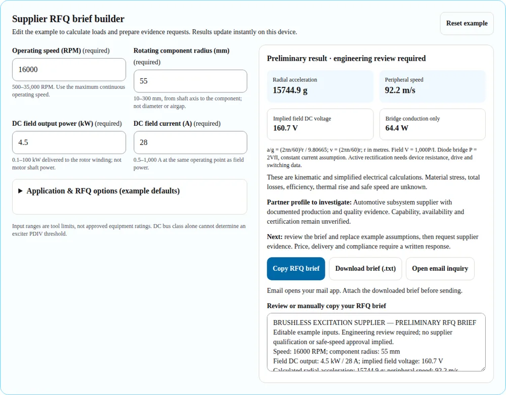
The tool uses deterministic kinematics for a component rotating at a fixed radius. Enter radius from the shaft axis, not diameter. Doubling speed multiplies radial acceleration by four; mass, geometry and material properties are still needed to turn that load into a stress analysis.
Field voltage is DC output power divided by DC current at the same operating point. The passive rectifier estimate assumes a full bridge with two conducting diodes, constant current and your stated forward drop. It excludes ripple, switching, winding, magnetic and primary-converter losses. Active rectifier losses are left unknown.
There is no readiness score, approved speed, inferred PDIV, service-life prediction or full-system efficiency estimate. The displayed values are an RFQ starting point. The input bounds only keep the calculator within its supported entry range.
Public-source review covers the listed abstracts, catalogue descriptions and manufacturer disclosures as of . Full standards, independent supplier audits and current commercial offers were not available for this review. Applicable standards and acceptance limits require project-specific confirmation.
Kinematics only: acceleration is not material stress, fatigue life, or a safe operating limit.
1. What the public evidence can tell a buyer
Use these organizations as technology references to frame supplier questions. This is not a verified vendor directory: there is no evidence here of open order books, independent supply of the exciter subsystem, current price or approved manufacturing sites.
On small screens, scroll the table horizontally.
1. What the public evidence can tell a buyer — known information, buyer evidence and limits
Reference
Known from the cited publication
Still needed before shortlisting
ORNL laboratory prototype
Rotary transformer plus rectifier demonstrated at high speed; maximum efficiency reported at a defined output.
A commercial design owner, reproducible test boundary, qualification route and production plan.
ZF I²SM concept
Hollow-shaft integration and an architecture-specific axial-space comparison.
Written availability, subsystem supply scope, shaft compatibility and latest development status.
MAHLE magnet-free motor
Contactless transfer disclosed at motor level.
Whether the requested subsystem is offered, interface drawings and excitation-only performance evidence.
Evidence to shortlist. Qualitative buyer workflow; no measured performance implied.
Boundary / action: Separate research results, manufacturer announcements and your supplier’s contractual test evidence. Only the last can resolve a sourcing decision for your specific program.
The tool addresses contactless rotary-transformer excitation for a wound rotor. Conventional synchronous-generator brushless exciters with an AC exciter and rotating diode wheel need a different electrical model. Describe that architecture explicitly in an inquiry rather than applying the bridge estimate to it.
On small screens, scroll the table horizontally.
2. Packaging and technology alternatives — known information, buyer evidence and limits
Architecture
Potential reason to investigate
Integration tradeoff / evidence request
In-rotor inductive transfer
Use internal shaft volume when axial space is constrained.
Verify bore dimensions, retention, assembly access and oil path. No fixed length saving is assumed.
End-of-shaft inductive transfer
Evaluate an accessible, separate module on a shaft extension.
Check bearing loads, overhang and service access. Lower tooling cost is not established without quotations.
Slip rings and brushes
Retain as a serviceable contact-based alternative where suitable.
Ask for contamination controls, inspection interval and lifecycle cost; no universal brush life is assumed.
Conventional AC exciter + diode wheel
Relevant to many industrial and generator procurement briefs.
Request field forcing, response and protection requirements; the tool’s simple passive full-bridge model may not apply.
Architecture decision path. Qualitative buyer workflow; no measured performance implied.
Boundary / action: Architecture selection is an engineering comparison. ZF’s disclosure supports one integration approach; it is not a general dimension or cost specification for other products.
3. Decide who owns design, manufacturing and qualification
“Supplier” can mean a component fabricator, subsystem integrator or complete e-drive partner. Contract the actual work package. A tier label alone does not establish design authority, quality capability or warranty responsibility.
On small screens, scroll the table horizontally.
3. Decide who owns design, manufacturing and qualification — known information, buyer evidence and limits
Engagement
Buyer must supply or assign
Supplier evidence to request
Turnkey subsystem
Performance envelope, interfaces, fault response and acceptance authority.
Design ownership, controller scope, thermal and mechanical validation, sub-tier list.
Build to print
Released drawings, material specifications and approval of deviations.
Process feasibility, inspection plan, revision control and traceable first articles.
Licensed IP / internal production
Transfer rights, manufacturing site and internal test ownership.
License restrictions, process transfer package and validation support.
Aerospace development
Program-specific airworthiness and assurance requirements.
Relevant development heritage, configuration control and material traceability; a quality certificate alone is insufficient.
Responsibility before tier labels. Qualitative buyer workflow; no measured performance implied.
Boundary / action: Editorial procurement framework. Confirm quality certificate validity, site and scope directly; this page does not certify any organization or infer FAA/EASA approval from AS9100D.
4. Turn the load result into a mechanical evidence request
The tool calculates acceleration at the entered component radius. It does not model ferrite stress, potting voids, solder fatigue, shaft critical speeds or containment. A low result cannot approve a rotor, and a high result cannot select a material by itself.
On small screens, scroll the table horizontally.
4. Turn the load result into a mechanical evidence request — known information, buyer evidence and limits
Item
What to establish
Acceptance ownership
Speed and radius
Continuous, transient and test speeds; maximum component radius and tolerance.
Buyer and machine designer agree the full operating envelope.
Retention and fatigue
Geometry, mass distribution, material properties versus temperature and assembly stresses.
Responsible rotor engineer approves analysis and representative testing.
Balancing
Rigid versus flexible behaviour; correction planes, residual unbalance and reporting method.
Agree the appropriate method and grade for the actual machine.
Overspeed / containment
Test factor, duration, temperature, instrumentation and failure containment.
Approved test plan; do not infer a universal 1.2× factor from this page.
Kinematics to validation. Qualitative buyer workflow; no measured performance implied.
Boundary / action: ISO 21940-11 addresses rigid-rotor balancing. It does not cover flexible rotor balancing or make a balance report proof of structural life.
5. Build an insulation plan from the exciter waveform
A traction bus label does not establish what voltage appears across every excitation insulation barrier. Record how the exciter is supplied and switched, the winding voltage, transients, grounding, isolation boundary, temperature and operating pressure.
On small screens, scroll the table horizontally.
5. Build an insulation plan from the exciter waveform — known information, buyer evidence and limits
Question
Evidence to request
Why it changes the decision
Where is the barrier?
Primary-to-secondary, winding-to-core and conductor-to-conductor insulation drawing.
Different barriers can experience different stresses and require different tests.
What waveform reaches it?
Measured repetitive peak, rise time, frequency and fault transient envelope.
DC bus voltage alone cannot yield a reliable PDIV or creepage requirement.
Which test is applicable?
Applicable standard edition, specimen, conditioning, measurement sensitivity and acceptance criteria.
IEC winding-insulation scope is not automatically a complete exciter-product qualification.
What environment applies?
Hot and cold operation, pressure/altitude, contamination and fluid contact.
A room-temperature result is incomplete if service conditions differ.
Insulation coordination inputs. Qualitative buyer workflow; no measured performance implied.
Boundary / action: The IEC public catalogue supports the winding-insulation scope. Numeric test limits require the applicable full standard, the insulation design and the project’s engineering approval.
6. Validate the exact fluid, material and bonded assembly
“Oil compatible” is incomplete without a named fluid formulation, material batch, exposure condition and measured property. Consider fresh and aged fluid where the duty requires it, and evaluate electrical and mechanical properties after exposure.
On small screens, scroll the table horizontally.
6. Validate the exact fluid, material and bonded assembly — known information, buyer evidence and limits
Test object
Evidence
Boundary
Rubber seals / elastomers
Before-and-after liquid-exposure properties using an agreed applicable method.
ISO 1817:2026 covers vulcanized and thermoplastic rubber.
Potting resin and adhesive
Material-specific swelling, adhesion, cracking and electrical measurements.
Do not treat a rubber test reference as blanket approval of epoxy or bond strength.
Rotating assembly
Thermal cycles, fluid exposure, retention and electrical retest under an approved sequence.
Coupon compatibility does not establish service life or centrifugal integrity.
Fluid qualification sequence. Qualitative buyer workflow; no measured performance implied.
Boundary / action: No universal 1,000-hour / 130°C protocol or swelling limit is asserted. Agree conditions and limits for your duty and materials before obtaining comparable supplier offers.
Treat this as a proposed buyer checklist, not a universal APQP, PPAP or VDA acceptance rule. Choose the quality framework and customer-specific deliverables in the contract. A certificate and a successful bench test answer different questions.
On small screens, scroll the table horizontally.
7. Use evidence gates from sample to production — known information, buyer evidence and limits
Gate
Required decision evidence
Hold point
Feasibility
Interface drawing, stated assumptions, identified technical gaps and design ownership.
Do not nominate on an efficiency headline alone.
Prototype validation
Representative unit test conditions, raw results, failures and corrective actions.
Do not replace missing spin or insulation evidence with component certificates.
Process readiness
Control plan, inspection methods, measurement capability and material traceability.
Agree actual process capability targets rather than borrowing a generic Cpk number.
Production release
Approved drawing revision, agreed submission package, capacity plan and change control.
Release only the validated site, process and configuration.
Ongoing supply
Lot traceability, agreed notification of changes, warranty feedback and revalidation triggers.
Resolve unapproved material, tooling or sub-tier substitutions before shipment.
Proposed quality gates. Qualitative buyer workflow; no measured performance implied.
Boundary / action: Do not infer safety integrity levels, flight approval, class-society acceptance or product reliability from a quality-management certificate. Confirm each program requirement with its responsible authority.
8. Compare commercial offers without invented price bands
Public sources reviewed here do not establish comparable brushless-exciter unit prices, regional cost advantages, tooling NRE or delivery intervals. Mark these as unknown until suppliers quote the same scope, quantity, currency, date and acceptance plan.
On small screens, scroll the table horizontally.
8. Compare commercial offers without invented price bands — known information, buyer evidence and limits
Cost / schedule item
Normalize in the RFQ
Risk to resolve
Unit price
Annual quantity, ramp schedule, included electronics, test and scrap assumptions.
A bare transformer and a qualified subsystem are not comparable offers.
NRE and tooling
Design hours, dies, molds, fixtures, software, ownership and replacement terms.
Low piece price may hide unrecoverable tooling or licensing obligations.
Qualification
Test specimens, laboratory time, failure analysis and repeat-test responsibility.
Unfunded validation can invalidate both budget and launch timing.
Delivery
Milestones for design freeze, samples, tooling, validation and capacity release.
A prototype promise is not a production delivery commitment.
Lifecycle
Service access, spare parts, warranty scope and engineering-change costs.
Removal of brush wear does not remove all failure or maintenance mechanisms.
Second source
Transfer rights, drawing access, alternate materials and revalidation cost.
Duplicated tooling without validated equivalence is not interchangeable supply.
Comparable offer workflow. Qualitative buyer workflow; no measured performance implied.
Boundary / action: Editorial commercial framework. Obtain dated quotations and test commitments; this page gives no current market price or lead-time estimate.
Risk and tradeoffs before supplier nomination
Misuse of calculations
Acceleration and a diode loss estimate can look like qualification. Mitigate by attaching the full duty, design assumptions and an approved validation plan. Hold release until test gaps are closed.
Budget and schedule gaps
A bare component quote can exclude retention, electronics and validation. Ask for an itemized complete scope and dated milestones; compare a serviceable existing architecture if redesign exceeds the program window.
Application mismatch
Automotive, aerospace and industrial generator duties need different evidence. Match the exciter architecture, quality framework and acceptance authority before selecting the supplier profile.
Single-source tooling and IP
Copying a die does not guarantee interchangeable parts. Negotiate access and transfer rights, identify alternate materials and budget the required validation before calling a backup source qualified.
Editorial risk checklist; no failure-frequency dataset or regional cost ranking is available from the sources reviewed.
Reproduce the RFQ tool example
Software execution captured on 2026-10-29: 16,000 RPM, 55 mm component radius, 4.5 kW field output, 28 A and 1.15 V per diode. Expected: 15,744.9 g, 92.2 m/s, 160.7 V and 64.4 W conduction loss. The isolated tool capture excludes site navigation and floating contact controls. This demonstrates software arithmetic, not hardware tests, customer results or supplier approval. Use Reset example to reproduce.
Worked sourcing scenarios
Illustrative decision exercises, not customer case studies or reported certification outcomes.
Wet automotive e-axle
Premise: Illustrative inputs: 16,000 RPM, 55 mm component radius, 4.5 kW field output and 28 A.
Process: The tool gives about 15,745 g, 92.2 m/s and 160.7 V field DC. At an assumed 1.15 V per diode, full-bridge conduction is 64.4 W; other losses are unknown.
Decision: Request oil-specific material evidence, rotor validation and the actual exciter voltage waveform. These calculations cannot release a production rotor.
Aerospace development
Premise: An illustrative program needs contactless excitation in an unpressurized installation. Speed and power alone do not describe the operating envelope.
Process: Select aerospace and confirm the quality choice. Add altitude, pressure, temperature, fault behaviour and traceability requirements to the downloaded brief.
Decision: Ask the responsible program team to define the qualification basis. No flight certification, DO-160 test pass or service result is claimed.
Industrial generator retrofit
Premise: An existing synchronous machine needs an excitation replacement with limited outage time. The architecture may use a conventional AC exciter rather than a rotary transformer.
Process: First record field voltage/current, excitation response, forcing, interfaces and installed clearances. Exclude the tool’s bridge-loss result if the actual rectifier topology differs.
Decision: Compare a compatible service replacement with a redesigned contactless subsystem. Include integration, validation and outage costs; do not assume a drop-in upgrade.
Sources, dates and evidence boundaries
Verified against public primary-source descriptions on . Manufacturer statements are attributed, historical and architecture-specific. Current availability remains unverified. Standard catalogue scopes support applicability questions, not invented numerical pass/fail limits.
Oak Ridge National Laboratory / APEC 2026 · 2026 conference paper
Supports: Laboratory prototype: testing up to 20,000 RPM and 25 A; reported maximum efficiency 96% at 7 kW output.
Does not establish: The abstract does not establish an airgap specification, continuous production rating, service life or an available supplier product. Do not assume all maxima occurred simultaneously.
Supports: I²SM concept integrates excitation inside the rotor; ZF reports up to 90 mm less axial space versus common separately excited motors and describes circulating-oil rotor cooling.
Does not establish: Historical manufacturer disclosure. Its stated development plan is not evidence of current series availability, a stand-alone exciter offering, or a saving achievable in your shaft.
Supports: Manufacturer describes contactless power transfer in its magnet-free motor and reports motor efficiency above 95% at almost all operating points.
Does not establish: Motor-level manufacturer statement, not an independently measured rotary-transformer efficiency map, package dimension, tooling quotation or current delivery commitment.
IEC public catalogue (also lists amendment 1:2019) · 2014 base / 2019 amendment
Supports: Qualification and quality-control scope for converter-fed AC-machine stator and rotor winding insulation.
Does not establish: Scope is not automatic applicability to every exciter component. The public abstract does not set a universal 1,850 V PDIV or creepage distance for an 800 V bus. Agree the applicable edition and test method with the machine insulation engineer.
Supports: Methods for comparing rubber properties before and after liquid exposure; catalogue lists the 2024 edition as withdrawn.
Does not establish: Rubber scope does not automatically qualify epoxy potting, adhesives or a complete rotating assembly. No universal ATF exposure duration, temperature, swelling or dielectric-retention acceptance value is established here.
ISO public catalogue (lists amendment 1:2022) · 2016 base / 2022 amendment
Supports: Procedures and residual-unbalance tolerances for rotors with rigid behaviour, including correction planes and balancing errors.
Does not establish: Flexible rotors are outside this part. The catalogue does not mandate G1.0 for all exciters or replace a rotor-specific overspeed and retention validation plan.
Buyer questions and next steps
Scope and sourcing
What does a brushless excitation supplier need to supply?
Define the work package: transformer, rotating rectifier, primary converter, controller, mechanical retention, cooling interfaces and validation can have different owners. Request a responsibility matrix before comparing offers.
Are ZF and MAHLE verified suppliers for my RFQ?
No. Their cited disclosures are technology references. This page does not verify current subsystem sales, capacity, certification, pricing or delivery. Contact each candidate to confirm scope and availability in writing.
Is brushless excitation always a rotary transformer?
No. A conventional brushless synchronous-machine exciter can use an AC exciter and rotating diode wheel. This tool focuses on contactless rotary-transformer sourcing; its full-bridge loss model must not be applied to a different rectifier topology.
Does an in-rotor design always save 90 mm?
No. ZF reported up to 90 mm for its concept against its stated motor baseline in 2023. Your result depends on the shaft, bearings, windings and cooling interfaces. Obtain complete package drawings.
Calculations and limits
How is radial acceleration calculated?
Angular speed is 2π times RPM divided by 60. Multiply its square by component radius in metres and divide by 9.80665 to express acceleration in g. This does not calculate stress or safe speed.
Why does the tool ask for field power and current?
Their ratio gives the implied DC field voltage at the chosen operating point. Use excitation output power rather than motor shaft power, and use current from that same duty point.
How is rectifier loss estimated?
For a passive full bridge with two conducting diodes and constant current, conduction loss is 2 times assumed forward drop times DC current. It excludes switching, magnetic, winding and converter losses. Use operating-temperature device data.
Why is active-rectifier loss not estimated?
An active stage needs switch on-resistance, current waveform, switching frequency, gate-drive and commutation data. A fixed equivalent diode drop would imply accuracy that these inputs cannot support.
Is the result a supplier qualification score?
No. The tool calculates a small set of physical quantities and creates evidence requests. It does not score supplier readiness, certify compliance, estimate total efficiency or approve a rotor design.
Qualification and next steps
Does an 800 V bus require a fixed PDIV value?
A bus label alone is insufficient. Identify the actual exciter insulation barrier, repetitive peak waveform, transients, temperature and pressure. Agree the applicable standard and test limits with the responsible insulation engineer.
Does ISO 1817 qualify all oil-immersed potting?
No. The 2026 edition covers methods for evaluating rubber in liquids. Potting resins, adhesives and complete assemblies need applicable tests and project-specific limits for the exact fluid and duty.
Is G1.0 balancing or 1.2× overspeed always mandatory?
This page establishes neither requirement. Agree rotor behaviour, balance grade, correction planes and an overspeed plan for the actual machine. ISO 21940-11 addresses rigid-rotor balancing and is not a structural-life approval.
What price and lead time should I put into a budget?
They remain unknown without a scoped quotation. Request separate unit price, design NRE, tooling, qualification cost and dated sample/production milestones, including quantity, currency and delivery terms.
What if clipboard access or email is unavailable?
The generated brief remains visible for manual selection and can be downloaded as a text file. Use the contact page if no mail app is configured. No inquiry is sent automatically.
What should I add before sending the brief?
Replace example inputs and add drawings, duty cycle, peak and transient loads, environment, insulation requirements, annual quantity, delivery location and target dates. Have the responsible engineer agree acceptance criteria.
Send a scoped supplier inquiry
Bring the RFQ brief, interface drawings, field duty, fluid and insulation conditions, requested quality evidence, annual quantity, delivery location and target dates. Our next step is a scope and feasibility discussion; capability, certification, quotation and delivery need written confirmation.
Review policy: revisit these sources by 2027-04-29, or sooner after a standard revision, source withdrawal or change in the calculation method. Send corrections through the contact page.