
Active De-Excitation and Inverter Fault Safety in Magnet-Free EESMs: ISO 26262 ASIL-D, 4-Quadrant Field Forcing, and Crowbar RFQ Guide
Specify active de-excitation for magnet-free EESMs. Compare field forcing, crowbar discharge and inverter fault safety; use the RFQ checklist to request review.
The short answer: Active de-excitation gives a magnet-free externally excited synchronous motor (EESM) a way to reduce rotor field current after an inverter fault. It does not make the drive inherently safe. Buyers should compare reverse voltage forcing, resistor discharge, and clamp circuits against the project's current, voltage, torque, and fault reaction limits. ISO 26262 ASIL D does not prescribe a universal 40–60 ms field-discharge deadline or certify a circuit topology. The vehicle safety analysis determines the relevant safety goals and timing requirements.
This engineering procurement guide helps drivetrain sourcing teams, functional safety leads, and e-axle engineers specify the field controller alongside the wound rotor. It provides reproducible screening calculations and the evidence to request before accepting a supplier's safety claim.
Published / last reviewed: November 8, 2026. Region/language: Global / English. Scope: EESM traction-drive selection and component RFQs. The circuit models can inform industrial wound-rotor screening, but automotive ISO 26262 claims do not automatically apply to industrial machinery. Evidence limits: All numerical examples below are illustrative calculations with stated inputs, not measured motor performance, customer results, or certification. They exclude saturation, stator coupling, eddy-current effects, and switching parasitics unless stated. Program-specific HARA, fault injection, and dynamometer testing remain necessary.
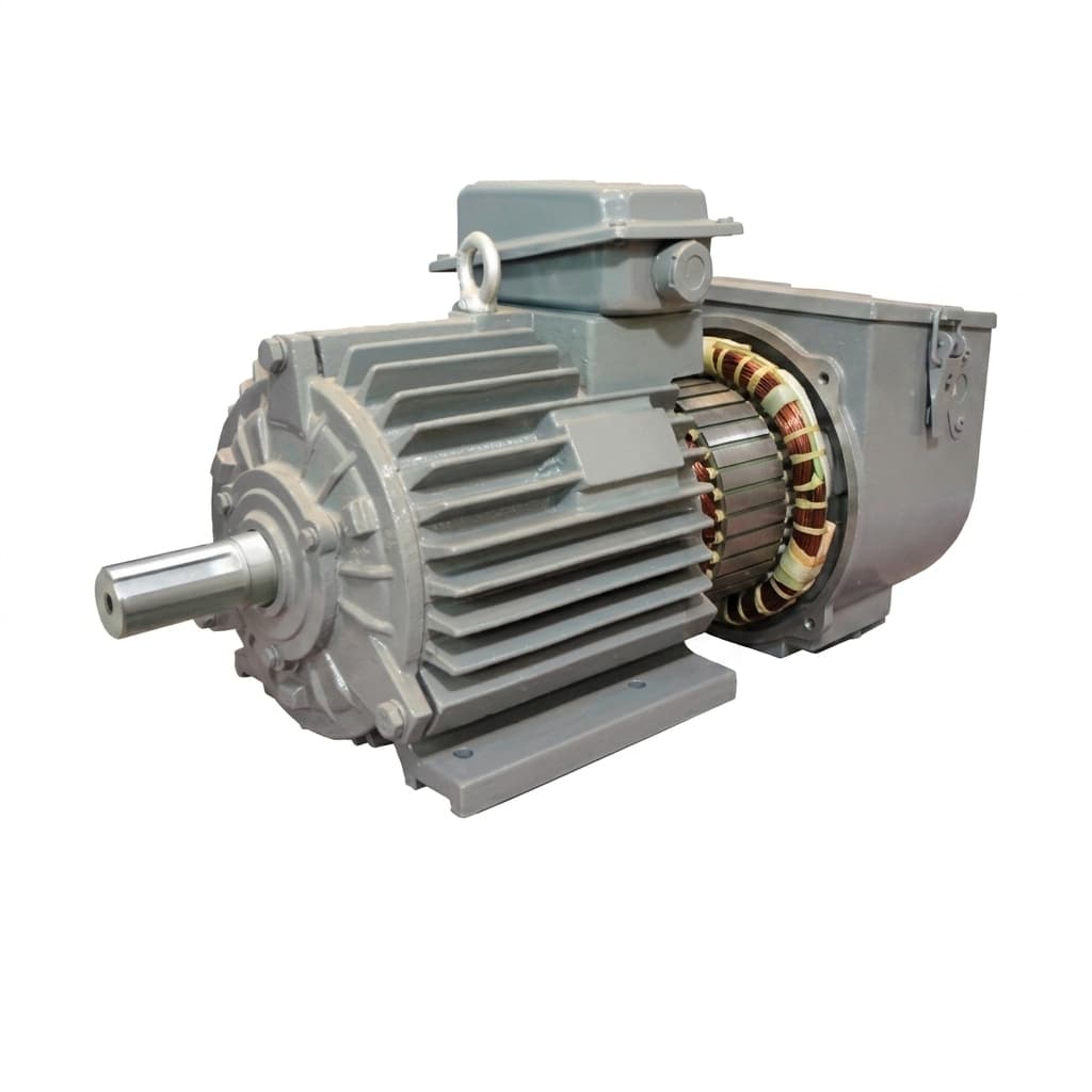
Existing catalogue illustration for component discussion. It does not document a tested rotor, a particular excitation topology, or ASIL-D qualification; use the schematic below to discuss fault handling.
For related specifications, review brushless excitation system manufacturing capabilities, automotive traction motor supplier evaluation, high-speed rotor containment sleeves, direct rotor oil cooling, 800V SiC inverter insulation and PDIV screening, and contactless versus slip-ring excitation RFQ trade-offs.
Preparing a traction-drive RFQ? Send your rotor envelope, DC bus voltage, and allocated fault reaction budget for a manufacturing feasibility review.
1. Inverter Fault Safety: Uncontrolled Generation, ASC, and Controllable EESM Flux
For a simplified sinusoidal machine model, the open-circuit stator phase back-EMF peak is:
E_phase,peak = p · ω_m · Ψ_rotorHere p is pole-pair count, ω_m is mechanical angular speed in rad/s, and Ψ_rotor is peak rotor-produced phase flux linkage. Use the same voltage convention throughout the RFQ: line-to-line peak voltage is approximately √3 times phase peak voltage in this ideal model. Rectifier conduction depends on instantaneous line-to-line EMF relative to DC-link voltage and diode drops; comparing phase peak directly with the DC bus can give the wrong threshold.
If sufficient EMF remains when all inverter switches are off, the antiparallel diodes can rectify current into the DC link. Whether this causes overvoltage depends on speed, flux, impedance, capacitance, battery acceptance, and protection. A disconnected battery or a supply unable to absorb energy can make this condition more difficult to control. Neither a specific current nor a destructive voltage follows from speed alone.
An active short circuit (ASC) connects the stator phases together through an available inverter switching path. It can reduce rectified feed-in to the bus, but creates stator current and transient torque that need validation. It is not available for every failed power stage or lost gate supply. A shorted switch, for example, changes which commands remain physically possible. Do not prescribe ASC as the answer to every inverter failure.
An EESM adds a controllable field circuit. In a linear approximation, Ψ_rotor = M_f · i_f; reducing field current reduces the field-produced EMF. This can make a later transition to an open-switch state possible. Residual magnetism, stator transients, reluctance effects, and mechanical drag mean that zero measured field current does not prove exactly zero shaft torque or voltage. Request measured release thresholds across the operating envelope rather than a promise of risk-free coasting.
2. Rotor Inductance, Stored Energy, and the Project FTTI Budget
The first supplier inputs are field inductance L_f, winding resistance R_f at defined temperatures, and maximum initial field current I_f0. Obtain an inductance map or conservative bounds where saturation and operating point matter. A single room-temperature inductance value is only a starting point.
For a linear, uncoupled field winding:
Stored magnetic energy E = 0.5 · L_f · I_f0²
Passive decay: L_f · di_f/dt + R_f · i_f = 0
Time constant τ = L_f / R_f
Time to 5% current t_5% = ln(20) · τ ≈ 2.996 · τ
Illustrative passive-decay calculation: With L_f = 80 mH, R_f = 1.6 Ω, and I_f0 = 30 A, stored energy is 36 J, the time constant is 50 ms, and time to 5% current is approximately 149.8 ms. If resistance is instead 1.0 Ω with the same inductance, time to 5% becomes 239.7 ms. These are assumed resistance values, not measured temperatures or an industry-wide timing range. A conducting diode adds a voltage drop and changes the low-current tail.
The Fault Tolerant Time Interval (FTTI) comes from the item's hazardous-event analysis; it is not a fixed number assigned to every ASIL-D motor. The ISO 26262-5 hardware-development record establishes the hardware-safety scope, not a universal EESM discharge time. Obtain the applicable safety requirements and agreed standard editions from the responsible system integrator.
For budgeting, separate detection, decision, actuator transition, verification, and margin. Example only: a project with a 50 ms limit might allocate 3 ms to detection and logic, 5 ms to verification and margin, leaving 42 ms for the physical transition. The passive example above exceeds that assumed allocation. Another project may have different limits or other mechanisms. Also, 5% field current is a calculation endpoint, not automatically an acceptable torque or back-EMF threshold.
3. Visual Architecture: Inverter Safe-State Selection and Field De-Excitation
This conceptual sequence shows the decisions to verify. Stages can overlap; ASC is conditional on the available hardware and the validated safety concept. The diagram is not a timing trace or a mandatory ISO sequence.
Read the figure with Sections 2 and 7: release depends on the measured hazard limits, not solely on a field-current percentage.
4. Field De-Excitation Topologies: Reverse Forcing, Crowbar Resistors, and Clamps
The useful comparison is how each circuit imposes an opposing field voltage and where the energy goes. The following are ideal circuit models, not construction instructions. Texas Instruments' SNVAA45 application brief supports the general trade-off: freewheeling is slow, stronger clamping shortens discharge, and energy recovery requires a suitable receiving supply. Its industrial-load example does not qualify an EESM traction drive.
Passive Freewheeling Diode: Establish the Baseline
A diode across the field winding provides a continuation path after the source is disconnected. While current remains positive:
L_f · di_f/dt = -R_f · i_f - V_diodeIgnoring the diode gives the exponential model in Section 2. A low clamp voltage can protect a switch yet produce a long discharge. Accept or reject this arrangement against the actual allocated timing and hazard limits. A passive diode is neither universally prohibited nor evidence of ASIL-D compliance.
Asymmetric Two-Quadrant Chopper: Negative Voltage Without Negative Current
A suitable two-switch, two-diode asymmetric bridge can provide positive and negative field voltage while current remains unidirectional. When its discharge diodes connect the winding back to the excitation rail, the winding sees approximately -V_exc. Not every circuit called a half-bridge has this capability; request the actual current paths and fault states.
For constant reverse voltage magnitude V_rev, constant L_f and R_f, and positive initial current:
L_f · di_f/dt = -V_rev - R_f · i_f
i_f(t) = (I_f0 + V_rev/R_f) · exp(-R_f · t/L_f) - V_rev/R_f
Time to zero: t_zero = (L_f/R_f) · ln(1 + R_f · I_f0/V_rev)
Time to threshold I_th:
t_th = (L_f/R_f) · ln[(V_rev + R_f · I_f0)/(V_rev + R_f · I_th)]
Worked calculation: Use L_f = 60 mH, R_f = 1.5 Ω, I_f0 = 30 A, and V_rev = 48 V. Stored energy is 27 J; the exact constant-parameter model gives 26.46 ms to zero and 24.62 ms to 5% current. Passive decay to 5% with these same winding parameters takes 119.83 ms. Always compare the same endpoint.
The reverse-forcing result can fit the illustrative 42 ms actuator allocation, but excludes switching delays and verification. Winding resistance dissipates some energy; the rest reaches the rail through the bridge. A supply that sources current does not necessarily sink it. As a conservative screening bound, depositing the full 27 J into an isolated 10 mF capacitor initially at 48 V would raise it to about 87.7 V, from V_final = sqrt(V_initial² + 2E/C). Actual energy partition changes that rise; the receiving rail still needs a verified absorption path.
Active Four-Quadrant H-Bridge: Voltage and Current Authority
An H-bridge can provide both voltage polarities and both current directions when appropriately controlled. Field discharge itself only needs negative voltage while the existing positive current decays; four-quadrant operation is not inherently necessary for that task. More switches can add control options, packaging, diagnostics, and failure modes.
For the same 60 mH, 1.5 Ω, 30 A example with 200 V reverse forcing, the exact model gives 8.12 ms to zero and 7.67 ms to 5% current. This is an assumed rail, not a typical product specification. The controller must prevent unwanted reverse current, handle dead time and commutation, and retain a discharge route if its gate drive or supply fails. Semiconductor voltage depends on the full circuit and overshoot, not merely the nominal excitation voltage.
Crowbar Discharge Resistor: Size the Loop and Pulse Energy
Here, “crowbar” means a switched resistive field-discharge path, not a zero-ohm short. The excitation source must be isolated as intended, and any lower-voltage freewheel path must be commutated so it does not bypass the discharge resistor.
τ_discharge = L_f / (R_f + R_c)
t_5% = ln(20) · L_f / (R_f + R_c)
Initial field terminal voltage ≈ -I_f0 · R_c
Initial resistor power = I_f0² · R_c
Resistor energy E_Rc = E_initial · R_c/(R_f + R_c)
With L_f = 80 mH, R_f = 1.6 Ω, I_f0 = 30 A, and R_c = 8 Ω, the ideal time to 5% is 24.96 ms. Initial terminal voltage is -240 V, initial resistor power is 7.2 kW, and the resistor dissipates 30 J of the initial 36 J; the winding dissipates the remainder. Rating the resistor for the full initial energy can be a conservative design choice, but 100% external dissipation is not a physical rule.
Increasing R_c to 30 Ω gives approximately 7.58 ms to 5%, with an initial -900 V terminal voltage. This is the intended resistive discharge voltage, separate from parasitic switching overshoot. Check pulse shape, temperature derating, repetition interval, and cooling using the component's data. A continuous wattage rating cannot establish single-pulse capability.
TVS or Zener Clamp: Ensure the Clamp Actually Conducts
A properly connected clamp can impose an opposing voltage without energy recovery. Size it for pulse current, temperature, pulse duration, and repetitive energy rather than a nominal breakdown voltage alone. A low-voltage diode loop can prevent the intended TVS threshold from being reached. A clamp across the whole winding also cannot independently prove acceptable turn-to-turn stress. Ask for a schematic and measured commutation waveform before treating this as a usable discharge mechanism.
5. Engineering Comparison Matrix for Supplier Submittals
These entries describe circuit behavior. Numerical timing must be calculated for the supplier's winding and then validated. No column is an ASIL certification.
| RFQ parameter | Passive diode | Asymmetric 2-quadrant bridge | 4-quadrant H-bridge | Resistive crowbar | TVS / Zener clamp |
|---|---|---|---|---|---|
| Discharge driver | Winding resistance and diode drop | Negative rail voltage | Commanded negative voltage | Added loop resistance | Clamp's opposing voltage |
| Timing model | Approximately L/R decay | Constant reverse-voltage model | Same model while current is positive | L/(R + R_c) decay | Reverse-voltage model with actual clamp curve |
| Reverse terminal voltage | Approximately one diode drop | Approximately -V_exc | Controlled, rail-limited | Initially -I_f0 · R_c | Depends on clamp and circuit placement |
| Energy destination | Mainly winding and diode | Winding plus receiving rail | Winding plus receiving rail | Winding plus resistor | Winding plus clamp devices |
| Key fault question | Does decay meet allocated limits? | Can the rail absorb energy after a fault? | Does discharge survive loss of control power? | Does the path engage and isolate the source? | Is another path bypassing the clamp? |
| Insulation evidence | Actual terminal waveform | Reverse voltage plus overshoot | Switching waveform and common mode | Initial voltage and commutation overshoot | Maximum clamp voltage at pulse current |
| Semiconductor evidence | Voltage, current, thermal limits | Rail and commutation stresses | All switching and fault states | Circuit-specific blocking voltage and pulse SOA | Pulse energy, current, temperature, repetition |
| Contactless implementation | Depends on rectifier current paths | Needs a suitable rotating power stage | Needs control and a viable energy path | Can use a qualified rotating discharge circuit | Can use a qualified rotating clamp path |
| Safety acceptance | Project evidence required | Project evidence required | Project evidence required | Project evidence required | Project evidence required |
Selection rule: Compare a negative-voltage bridge when a receiving rail is available; compare dissipative discharge when reverse energy cannot be accepted. If the field is behind a passive rotating rectifier, identify the rotor-side discharge path first. Then check voltage, energy, mechanical qualification, and fault independence before comparing BOM price.
6. Contactless Exciters Versus Slip Rings: Where Can Field Energy Go?
With slip rings, the field winding is electrically accessible from the stationary side. A stationary bridge or discharge resistor can be easier to cool and instrument. Nevertheless, brush contact faults, wiring inductance, isolation, and loss of the excitation rail still belong in the fault analysis.
A contactless inductive system commonly transfers AC across an airgap and rectifies it on the rotor:
Stationary inverter -> rotary transformer -> rotating rectifier -> field winding
                                                    |-> qualified discharge path
A passive diode rectifier generally cannot reproduce a stationary controller's arbitrary negative DC command at the field winding. Cutting primary power therefore does not establish rapid rotor discharge. The remaining loop depends on the rectifier and transformer connections. If it contains winding resistance and two forward diode drops, its simplified equation is:
L_f · di_f/dt = -R_f · i_f - 2 · V_diodeThe voltage drops are added to the resistive voltage, not to the resistance itself. Current decays rather than remaining “fully magnetized” for a fixed duration.
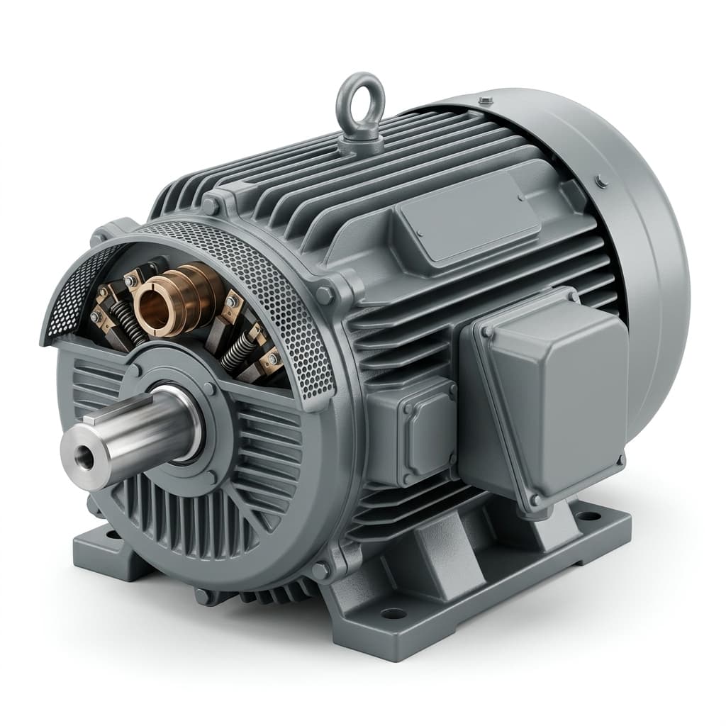
Catalogue illustration showing a shaft-side electrical interface. It is not a balancing test, insulation test, or measurement of the contactless architecture described above.
Possible rotor-side solutions include a switched resistor, a correctly arranged clamp, or an active rectifier with a compatible bidirectional transfer path. An active rectifier alone does not establish that the stationary converter can accept recovered energy. For each solution, request trigger behavior, local power availability, current-path continuity, and a response to a failed switch or sensor. Carrier-loss detection needs an agreed timeout that tolerates normal disturbances while meeting the allocated reaction time; no universal 200 μs value applies.
Rotating resistors and electronics also need retention, thermal, vibration, and overspeed qualification. Centrifugal acceleration follows a = ω²r, so the actual component radius matters. A generic g-rating or thermal-cycle count without mounting geometry and a mission profile is insufficient for supplier acceptance.
7. Coordinating Stator ASC and Rotor De-Excitation
A useful fault-state review separates three questions: can the inverter still command the chosen state, can the field energy be removed, and what evidence permits release? A possible sequence is:
- Detect and select: Identify the fault and command a validated containment state if the relevant devices and gate supplies remain usable. Some faults require a different protection path.
- Discharge and observe: Isolate the field source as required, engage the approved discharge path, and monitor field current, stator current, DC voltage, and torque or validated proxies. De-excitation may begin alongside stator containment.
- Verify before release: Open the stator switches only when speed-dependent EMF, bus behavior, current, and shaft-torque limits permit it. Account for sensor uncertainty and timeout behavior.
ASC can be useful while field-produced EMF is high, but it is neither always available nor always required. Opening all switches may be acceptable at a sufficiently low speed or flux, or where another validated mechanism absorbs the energy. Equally, low field current does not establish that a physically shorted inverter can enter an open-circuit state.
Procurement should request a state-transition table by fault type, not one universal shutdown trace. Include controller reset, excitation supply loss, DC contactor opening, sensor bias, and a stuck discharge switch. Each trace should identify initial speed, field current, winding temperature, bus condition, detection latency, peak torque, and the criterion used to end the test. The motor, field controller, inverter, and vehicle integrator need agreed ownership of these interfaces.
8. Rotor Insulation: Separate Voltage Stress from Thermal Class
Fast field-current decay and fast terminal-voltage edges are related but different specifications. Inductance sets voltage through L · di/dt; parasitic capacitance, switching edge rate, winding geometry, and reflections determine transient voltage distribution. A millisecond discharge does not imply a particular nanosecond voltage rise time.
For illustration, 800 V divided by 80 turns is an average of 10 V/turn. It does not establish the maximum voltage between adjacent turns. That requires a suitable winding model or representative impulse measurements. Specify winding-to-ground and turn insulation separately, including polarity reversal, common-mode voltage, temperature, coolant exposure, and repetitive duty.
Thermal class is not a surge-voltage rating. Class H denotes a 180°C thermal class; a wire designation or higher thermal index does not prove the completed insulation system withstands a specified impulse. Do not equate Class F with “500 V” or Class H with “1,200 V.” Ask for system-level test evidence rather than selecting enamel chemistry from those labels.
IEC 60034-18-41:2014+AMD1:2019 concerns Type I converter-fed AC-machine insulation qualification and quality control. Agree its applicability to the particular rotor field waveform and construction with the supplier and test laboratory. It does not impose the article's former universal 1,500 V / 50 ns acceptance condition for every EESM field coil.
An RFQ should define maximum repetitive terminal voltage, measured overshoot, rise time, pulse count, temperature, and the applicable test procedure. Include impregnation quality, fluid compatibility, and inspection acceptance criteria. Voids can contribute to partial discharge when local electric stress is sufficient; neither “100% void-free” resin nor a material trade name alone proves an adequate insulation system.
9. RFQ and Supplier Audit Checklist: EESM Field and Inverter Safety
Use this checklist to make supplier bids comparable. Record each limit as a project requirement, an analytical estimate, or a measured result.
- 1. Safety allocation: Attach the applicable safety goals, ASIL allocation where relevant, FTTI, and fault reaction budget. Define acceptable voltage and torque, rather than adopting a generic 5% field-current endpoint.
- 2. Winding input data: Request resistance versus temperature, inductance versus operating point, maximum initial field current, tolerances, and calculation assumptions.
- 3. Topology disclosure: Request normal and fault-state current paths, source isolation, energy destination, and the behavior of passive rectifiers and bypass diodes.
- 4. Voltage qualification: Declare reverse voltage, common-mode voltage, overshoot, device blocking stresses, pulse SOA, and the derating policy used for the actual circuit.
- 5. Insulation evidence: Agree the relevant standard and test waveform with the supplier. Request representative winding and assembled-rotor test reports with temperature and fluid-conditioning details.
- 6. Energy absorption: Provide winding energy, resistor or clamp pulse curves, receiving-rail limits, initial temperature, repeat events, and cooldown assumptions. Include an unavailable receiving rail.
- 7. Contactless discharge: Show the rotating current path and trigger mechanism. Request measured or validated rotor-current acquisition, carrier-loss behavior, and loss-of-local-power response.
- 8. Fault coordination: Provide a state table for ASC, open-switch operation, and fallback protection. Identify which faults disable each mechanism and who verifies the transition criteria.
- 9. Validation envelope: Supply fault-injection traces across agreed speed, current, temperature, and DC-bus conditions. Include sensor uncertainty, latency, peak shaft torque, and residual EMF.
- 10. Mechanical and release evidence: Qualify rotating component retention at the actual radius and overspeed, thermal mission profile, and fluid exposure. List unresolved deviations, safety documentation ownership, and change-control obligations.
Send your motor drawing, operating envelope, and allocated safety requirements for an EESM manufacturing feasibility review. Identify missing inputs so the initial quotation can state its assumptions.
10. Frequently Asked Questions
Q1: Must an EESM always enter ASC before opening its stator switches?
No. The correct state depends on speed, remaining flux, DC-link energy absorption, and the faulted hardware. ASC can reduce diode-rectified feed-in while the field decays, but it creates current and torque and needs a functioning switching path. Use the system's validated fault-state table. Neither EESM nor permanent-magnet drives have one mandatory safe-state sequence for all operating points.
Q2: Does faster de-excitation require Class H insulation?
Not by itself. Faster discharge can require higher opposing voltage, while switching overshoot can add further stress. Thermal class addresses a different property. Specify the complete voltage waveform and thermal mission profile, then obtain representative insulation-system qualification. A clamp at the winding terminals does not automatically bound every interturn voltage.
Q3: How can a brushless exciter remove field energy after primary power is lost?
It needs a defined continuation and discharge path. Possibilities include a rotating switched resistor, a correctly commutated clamp, or an active conversion system with an available energy destination. Ask how the mechanism triggers and remains functional without primary power. Do not infer discharge speed from “contactless” or “active rectifier” in a catalogue description.
Q4: How does -40°C affect passive field-current decay?
Using the approximate copper coefficient 0.00393/°C referenced to 20°C:
R(-40°C)/R(20°C) = 1 + 0.00393 · (-40 - 20) = 0.7642
τ(-40°C)/τ(20°C) = 1/0.7642 ≈ 1.309, if L is unchanged
Resistance is approximately 23.6% lower, making the ideal passive time constant about 30.9% longer. Reverse forcing reduces dependence on resistance when its voltage dominates, but still depends on minimum available voltage, inductance, tolerances, and device behavior. It does not guarantee a universal sub-30 ms response at every temperature.
Q5: Does ASIL D require redundant position or field-current sensors?
The ASIL label alone does not prescribe either arrangement. A field-discharge path can operate without rotor angle feedback, while verifying a safe drive state may require other monitored quantities. Redundancy, diagnostics, and independence follow from the safety requirements and failure analysis. A fast current trace or a duplicated sensor alone cannot demonstrate an ASIL-D safety case.
11. Sources and Evidence Limits
Public records checked: November 8, 2026. These three primary references support the limited subjects identified below. Public catalogue abstracts were checked for the standards; full normative requirements must be agreed using the applicable documents. The calculations in Sections 2 and 4 are this guide's ideal-model derivations, not published test results.
- ISO 26262-5:2018 — Hardware-level product development. Official scope record covering hardware safety requirements, design, architectural evaluation, and verification. It does not establish the numerical discharge examples as mandatory deadlines.
- IEC 60034-18-41:2014+AMD1:2019 CSV — Type I converter-fed insulation systems. Official qualification and quality-control scope, including stator/rotor windings in converter-fed AC machines. Applicability to a specific DC field circuit needs assessment.
- Texas Instruments SNVAA45 — Faster Switching of Large Inductive Loads in Digital Output Modules. Application brief on discharge voltage, heat, energy recovery, and receiving-supply considerations. Its components and industrial test conditions are not a traction-motor design approval.
No supplier field-discharge measurements or certification dossier are supplied here. Before a sourcing decision, request the circuit-specific evidence listed above and resolve deviations with the responsible system integrator.
Ready to Issue an RFQ for Magnet-Free EESM Stators and Wound Rotors?
Provide envelope dimensions, DC-link and excitation-rail limits, torque/speed profile, initial field current, interface preference, and the allocated fault reaction budget. These inputs support a manufacturing feasibility discussion and a quotation with explicit assumptions. Functional safety acceptance belongs to the program's documented engineering and validation process.
Contact the Magnet-Free Motor Engineering Team for a Technical Feasibility Review.
Author

More Posts
Rare Earth Price Forecast 2026: Why Motor Manufacturers are Abandoning Neodymium
A deep dive into the 2026 rare-earth pricing forecast. Learn why volatile Neodymium and Dysprosium markets are forcing OEMs to adopt magnet-free motors.

Thin-Gauge Electrical Steel Selection for High-Frequency Magnet-Free Motors: NO20, NO25, and Stacking Tech RFQ Guide
Compare NO20 and NO25 thin-gauge electrical steel for magnet-free motors. Review loss data, joining trade-offs, and the RFQ checklist before requesting a quote.

800V SiC Inverter Stress on Magnet-Free Motors: Stator Insulation, PDIV, and Bearing Protection Guide
Specify 800V SiC magnet-free motor insulation, PDIV/RPDIV evidence, and bearing protection. Compare options and use the RFQ checklist before requesting review.