
Direct Rotor Oil Cooling for High-Speed Magnet-Free Motors: Through-Shaft, Rotor Spray, and End-Winding Cooling RFQ Guide
Compare direct rotor oil cooling for magnet-free motors: shaft, spray and duct options, seal and fluid checks. Use the RFQ checklist to request a design review.
The short answer: Direct rotor oil cooling can help a magnet-free motor sustain output when rotor temperature limits its duty cycle. Compare a closed through-shaft circuit, centrifugal spray onto rotor end-windings, and internal rotor ducts against the actual loss map, oil supply, sealing, and drainage constraints. Cooling topology alone does not establish a continuous-to-peak power ratio, efficiency gain, or service life. Request comparable thermal and hydraulic test data before choosing an architecture.
This engineering procurement guide helps drivetrain program managers, thermal engineers, and Tier-1 sourcing teams prepare a rotor-cooling RFQ and identify the evidence needed to approve a design.
Published / last reviewed: November 2, 2026. Region/language: Global / English. Scope: Radial-flux EESM, SynRM, and brushless wound-field synchronous drivetrains, with screening examples for 10,000–22,000 rpm. Evidence limits: This is an engineering decision framework, not a report of measured motor or seal performance. Numerical examples below use stated assumptions. Public standards catalogue descriptions establish document scope; the purchased standards, customer requirements, and design-specific qualification determine acceptance limits. Review the specification when the fluid, winding insulation, speed envelope, or cited standard edition changes.
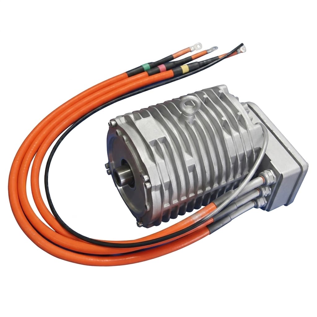
Product illustration for assembly context. The external view does not establish an internal oil-cooling circuit, rotor topology, or validated performance.
For related specifications, review our automotive traction motor supplier guide, brushless excitation system manufacturer guide, thin-gauge electrical steel RFQ guide, 800V SiC inverter insulation guide, and EESM vs. IPM procurement comparison.
Preparing an internally cooled motor RFQ? Send your continuous power target, maximum speed, and oil supply constraints for an engineering discussion.
1. The Thermal Asymmetry of Magnet-Free Motors
Start with the location and magnitude of losses rather than assuming every magnet-free rotor needs oil spray. An interior permanent magnet (IPM) rotor has no field winding copper loss, but magnet and rotor iron losses can still constrain operation. Its cooling needs depend on speed, harmonics, magnet grade, and duty cycle.
Magnet-free architectures change that thermal map:
- Externally excited synchronous motors (EESM): Rotor field coils dissipate Joule heat. At a stated operating temperature, rotor copper loss is
P_rotor,cu = I_f² × R_f(T). For an illustrative field current of 50 A and winding resistance of 1.2 ohm, the loss is 3,000 W. This is an assumed operating point, not a typical loss for every traction motor. - Synchronous reluctance motors (SynRM): There are no rotor field windings. Rotor iron loss and local heating depend on slotting, inverter harmonics, lamination material, and geometry. Speed alone does not determine loss or cooling need. Electrical fundamental frequency is
f = pole pairs × rpm / 60; four pole pairs at 18,000 rpm give 1,200 Hz.
The Airgap Thermal Bottleneck
Rotor heat can leave through the shaft, bearings, internal gas, and airgap. A stator jacket cools the stator effectively only if heat can reach it; rotor-to-stator heat transfer also depends on geometry and rotation-induced flow. Ask the supplier for a thermal network or correlated model that includes parallel heat paths and measured rotor hot spots.
For preliminary screening, temperature rise = loss × effective thermal resistance. Neither loss nor thermal resistance can be assigned from the motor topology alone. Compare jacket-only and internally cooled designs at the same torque-speed points, coolant inlet temperature, flow, ambient conditions, and thermal limits. Define both continuous operation and peak duration; their power ratio is not a universal cooling benchmark.
2. Direct Rotor Oil Cooling Architectures: 3 Practical Topologies
For oil that contacts motor electrical materials, select a fluid qualified with the actual insulation, copper, seals, and bearings. SAE J3200_202210 describes relevant properties and suggested test methods for lubricants in electrified geared drivetrains where the motor contacts the lubricant. It is an Information Report, not a universal fluid certification or a fixed pass/fail specification.
The following flow sketch distinguishes a closed shaft circuit from a wet rotor end-winding circuit. It is conceptual; the rotary interface may use a contacting seal or a controlled-clearance feed depending on design.
Conditioned oil -> filter -> feed interface -> hollow shaft
                                             |
  A: closed shaft circuit <------------------+
     lance -> shaft bore return -> heat exchanger
     heat conducts from rotor into shaft; cavity stays dry
                                             |
  B: wet end-winding circuit <----------------+
     radial outlets -> rotor end-turns -> drains
                    -> sump / scavenge -> heat exchanger

  C: internal ducts branch from a shaft distributor into
     the rotor core, then return or drain as designed.
Topology A: Coaxial Lance Through-Shaft Cooling (Dry Cavity)
A stationary lance feeds oil into a hollow rotating shaft. A separate annular return carries oil back to the manifold. In a closed design, oil remains inside the shaft circuit; heat from the rotor must conduct through the hub, interfaces, and shaft wall.
- Selection reason: Keeps coolant out of the airgap in normal operation and avoids spray contact with winding insulation.
- Main limitation: The winding-to-shaft conduction path may remain the thermal bottleneck, particularly for an EESM field winding.
- RFQ evidence: Cross-section showing supply and return separation, lance clearance under shaft deflection, interface thermal assumptions, pressure loss, and leak containment.
Topology B: Centrifugal Radial Spray / Jet Cooling (Wet Cavity)
Oil supplied through the shaft exits metered radial outlets toward the rotor end-windings. Rotation changes the flow distribution and available pressure. Coverage, residence time, insulation layers, and drainage determine whether the winding hot spot improves.
For an ideal liquid rotating as a solid body:
Δp = 0.5 × oil density × angular speed² × (outer radius² − inner radius²)
angular speed = 2π × rpm / 60
Example assumptions: 820 kg/m³, 18,000 rpm, inner radius 0,
                     outer radius 0.025 m
Ideal radial pressure rise ≈ 910,000 Pa = 9.1 bar
This is a theoretical pressure difference within rotating liquid, not a measured outlet pressure, required inlet pressure, or guaranteed spray pattern. A real open jet has slip, friction, aeration, and discharge losses; the inlet seal does not automatically see this calculated head.
- Selection reason: Brings coolant closer to rotor end-turn heat sources.
- Main limitation: End-turn wetting may leave the active winding length hot. Oil entering the airgap can increase drag.
- RFQ evidence: Flow distribution versus speed, winding temperature measurements, drain capacity under vehicle inclination, and total pump-plus-drag losses. A shaft-fed spray aimed at stator end-windings is not evidence of rotor winding cooling; identify the wetted component on the drawing.
Topology C: In-Lamination Internal Cooling Ducts
Distributors feed passages within the rotor stack, bringing oil closer to active-length heat sources. Ducts and seals must be assessed with the magnetic circuit and mechanical structure.
- Selection reason: Can shorten the heat path where shaft cooling or end-turn spray leaves an active-length hot spot.
- Main limitation: Passages alter magnetic and structural geometry; stack tolerances, sealing, cleanliness, and inspection become more demanding.
- RFQ evidence: Stress and electromagnetic analysis for the ducted rotor, correlated thermal results, channel inspection, leak tests, and thermal-cycle durability. There is no universal application restriction or performance advantage for this topology.
3. Architecture Comparison: Cooling Methods for Magnet-Free Rotors
Use this qualitative matrix to request comparable bids. It is not a set of supplier ratings. IEC 60034-6 classifies cooling arrangements; request the supplier's complete circuit description and applicable IC designation rather than assigning a code from “oil cooling” alone.
| RFQ decision | Stator water jacket baseline | Closed through-shaft circuit | Rotor end-winding spray | Internal rotor ducts |
|---|---|---|---|---|
| Primary heat path | Stator to housing; indirect rotor paths | Rotor to hub and shaft, then oil | Winding surface to oil | Core or slot region to passage wall and oil |
| Coolant contact | Jacket fluid isolated from cavity | Oil confined to shaft circuit | Oil contacts selected cavity materials | Oil contacts passage materials and possibly cavity |
| Main screening question | Can rotor hot spots meet the duty cycle? | Is conduction to shaft sufficient? | Does spray reach the limiting hot spot? | Does the duct benefit justify structural changes? |
| Continuous output evidence | Measured thermal equilibrium at agreed conditions | Same conditions, including shaft oil inlet | Same conditions, including flow split and drainage | Same conditions, including duct distribution |
| Thermal resistance evidence | Model correlated to rotor measurements | Include hub and shaft contact resistance | Include wetting and insulation resistance | Include channel-wall and insulation resistance |
| Drag and drainage | Assess gas windage and bearing losses | Check leakage into cavity | Measure oil drag across speed and inclination | Check leakage routes and return arrangement |
| Feed interface | No rotor oil feed required | Lance and return or rotary union | Feed interface plus metering outlets | Distributor plus channel seals |
| Cost comparison basis | Housing and coolant loop scope | Shaft machining, lance, feed and testing | Outlets, feed, drainage and fluid qualification | Rotor tooling, seals, inspection and yield |
| Approval evidence | Duty-cycle thermal validation | Thermal, leak and shaft validation | Thermal, drag, material and drain validation | Combined thermal, hydraulic and rotor-strength validation |
4. High-Speed Dynamic Rotary Seals: The 18,000 rpm Interface
Seal selection starts with the actual sealing diameter and pressure-temperature-speed envelope. A material name or shaft rpm alone cannot establish suitability or lifetime.
Rubbing velocity v = π × diameter × rpm / 60
Example: diameter 0.032 m, speed 18,000 rpm
v = 30.16 m/s
Use that value to obtain a supplier-approved operating envelope. Catalogue maximum pressure, speed, and temperature may not be permissible simultaneously.
| Feed / seal option | What to ask the supplier | Trade-off to validate |
|---|---|---|
| PTFE or engineered radial lip seal | Approved oil, counterface, rotation direction, runout, and combined pressure-speed envelope | Frictional heating, shaft wear, and leakage over the duty cycle |
| Mechanical face seal / rotary union | Face materials, pressure balance, cooling, axial motion, and packaging | Face wear, startup behavior, heat generation, and installation space |
| Controlled-clearance feed / bushing | Clearance across temperature and deflection, bypass flow, and return routing | Continuous leakage, pump demand, and cavity oil management |
Shaft Counterface Requirements
For a contacting seal, put the selected supplier's counterface requirements on the drawing: material/coating, hardness and case depth where needed, roughness parameters, permissible lead, runout, and installation protection. Do not copy one hardness or roughness value across different seal designs. Agree leakage limits, rotation reversals, contamination exposure, and endurance conditions before tooling release.
5. E-Fluid Compatibility: SAE J3200 and ASTM D130
In a wet motor, oil can contact enamel, impregnation resin, slot liners, copper, adhesives, and seals. The electrical insulation system still provides the designed insulation barrier. “Dielectric oil” does not replace winding insulation or establish inverter-pulse withstand capability.
Use SAE J3200 as a framework for fluid discussions. ASTM D130 screens relative corrosiveness to copper; a copper-strip result does not guarantee long-term winding compatibility. The linked D130-19 record is historical and lists D130-26 as active at review. Specify the contract edition, exposure conditions, and acceptance criteria with the customer and laboratory.
Key Fluid Parameters for Direct Rotor Cooling
| Fluid property | Evidence to request | RFQ acceptance decision | Limitation |
|---|---|---|---|
| Viscosity versus temperature | Fluid curve including cold-start conditions | Confirm pumpability, pressure loss and bearing needs | A 40°C viscosity cannot establish -40°C startup behavior |
| Density and heat capacity | Temperature-dependent supplier data | Size heat transport and oil temperature rise | Bulk heat removal does not establish winding hot spots |
| Copper corrosion | ASTM D130 report with edition, time and temperature | Agree the rating required for the actual materials | A 1a result is not proof of zero lifetime corrosion |
| Electrical conductivity / resistivity | Fresh and aged fluid data with test conditions | Agree an application-specific operating window | Lower conductivity alone does not establish system suitability |
| Dielectric breakdown | Named method, electrode geometry, gap, temperature and water content | Compare results using the same procedure | A kV value cannot be transferred between test methods |
| Enamel, resin and liner compatibility | Immersion/thermal-ageing results on the proposed material system | Agree electrical and mechanical property retention | A thermal class is not an oil-compatibility qualification |
| Seal and adhesive compatibility | Swelling, hardness and bond-retention results | Approve the actual formulations and interfaces | A generic elastomer family does not identify a qualified compound |
| Aeration, foaming and ageing | Fresh/aged fluid and return-loop test results | Validate drainage, lubrication and service strategy | Fresh-fluid bench data may miss contamination or ageing effects |
6. Fluid Dynamics: Flow, Pressure Drop, and Airgap Churning
Heat-Balance Example: Estimate Flow Before Sizing the Pump
For a hypothetical 3 kW rotor heat load, assume oil density of 820 kg/m³, specific heat of 2,000 J/(kg·K), and an allowed bulk oil rise of 20 K:
Volumetric flow = heat / (density × specific heat × temperature rise)
                = 3,000 / (820 × 2,000 × 20)
                = 0.0000915 m³/s ≈ 5.5 L/min
This energy balance assumes the allocated flow absorbs the full heat load. It excludes bypass leakage, uneven distribution, other shared-loop heat sources, and local thermal resistance. It is a reproducible sizing example, not a recommended flow for every motor.
Request the combined pump and circuit curves at cold start, low speed, maximum speed, and hot operation. Include the filter, feed interface, lance, outlets, heat exchanger, and return path. Centrifugal assistance changes with speed and cannot substitute for verified low-speed delivery. Pump input power depends on flow, pressure rise, and pump efficiency; include it when comparing cooling options.
Prevent Oil Accumulation in the Airgap
Oil touching a fast rotor can increase drag and heating. The penalty depends on viscosity, oil inventory, geometry, speed, and whether the flow is laminar, turbulent, or aerated; a density ratio alone cannot predict it.
Measure pump input and motor drag alongside rotor temperatures at controlled oil flow and temperature. Test vehicle pitch, roll, acceleration, and return aeration. Gravity drainage may be adequate in some packages; use active scavenging where drainage tests show it is needed. Size it against liquid and entrained-air return demand rather than prescribing a universal sump depth, drain diameter, or pump multiplier.
Before supplier nomination, share the proposed oil circuit and duty cycle for an RFQ review, including any unresolved flow, leakage, and material-compatibility assumptions.
7. B2B Sourcing & Engineering RFQ Checklist
Attach the same operating envelope and acceptance plan to every bid. Record the proposed value, evidence file, test conditions, and responsible owner for each item; leave unresolved values explicitly open.
Section A: Mechanical & Shaft Interface Specs
- Operating speed envelope: Continuous speed map, transient maximum, rotation direction, and customer-approved overspeed test.
- Hollow shaft and rotor integrity: Bore geometry, runout, deflection, rotor stress and balancing specification for the complete assembly.
- Feed and seal interface: Sealing diameter, combined pressure-speed-temperature envelope, counterface drawing, and permitted leakage.
- Packaging and return: Drive-end/non-drive-end access, lance clearances, return routing, service access, and fault containment.
Section B: Thermal & Hydraulic Specs
- Continuous and peak output: Torque-speed points, peak duration, coolant inlet conditions, ambient, hot-spot limits and thermal-equilibrium criterion.
- Flow and pressure: Pump/circuit curves, cold-start limits, filter losses, bypass leakage and shared-loop allocation.
- Wetted target: Identify rotor versus stator end-turns, active-length heat paths, distribution versus speed, and blockage detection.
- Drainage and losses: Oil inventory limits justified by testing, inclination envelope, return aeration, pump input and drag measurements.
Section C: Material & Chemical Compatibility
- Fluid identity: Exact product, formulation/change control, fresh/aged properties and test methods informed by SAE J3200; no generic “J3200 certification” claim.
- Copper compatibility: ASTM D130 contract edition, rating and exposure conditions, with any longer-duration winding-system corrosion study recorded separately.
- Insulation and seals: Actual enamel, liner, resin, adhesive and seal-compound qualification, including agreed ageing and electrical tests.
Section D: Quality & Factory Acceptance Testing
- Leak testing: Method, test pressure, temperature, acceptance limit and correlation to operating leakage; distinguish design qualification from production checks.
- Spin and endurance: Representative duty cycle, speed/pressure/temperature combinations, thermal cycles, leakage trend and teardown criteria.
- Cleanliness: Separate component particulate cleanliness from circulating-fluid cleanliness; specify measurement method, sampling point and limit for each.
- Supplier handover: Drawing revision, raw test data, calibration records, deviations, production controls and requalification triggers.
8. Frequently Asked Questions (FAQ)
What is the difference between stator cooling and direct rotor cooling?
A stator jacket removes heat through the stator and housing. Rotor cooling provides another path through the shaft, rotor surfaces, or internal passages. Which path matters most depends on the loss distribution and limiting hot spot; adding rotor cooling does not guarantee a fixed output increase.
Can water-glycol be used for direct rotor cooling instead of oil?
Distinguish a sealed internal passage from fluid sprayed onto electrical materials. A closed shaft circuit may use water-glycol if corrosion, leakage containment, and the complete design are qualified. Direct winding contact requires a fluid and insulation system designed and validated for that exposure. A water-glycol leak into a cavity intended for oil can compromise insulation; nominal coolant choice alone does not establish fault behavior.
How does direct rotor oil cooling affect motor efficiency at high speeds?
Lower winding temperature can reduce EESM copper loss at the same field current, while oil pumping, feed leakage, and drag add losses. SynRM has no rotor field copper loss to reduce. Compare net shaft output and total electrical input, including auxiliary pumps and excitation, at the same operating point. Cooling does not automatically increase overall efficiency.
What is the service life of a high-speed rotary seal at 18,000 rpm?
There is no universal lifetime at that speed. Sealing diameter, pressure, temperature, fluid, contamination, runout, starts, and reversals all matter. Request endurance data representative of your mission profile, agreed leakage and wear limits, and a service plan. A short qualification test cannot by itself prove a vehicle-lifetime claim.
How does direct rotor cooling perform during cold starts at -40°C?
Check the selected fluid's cold-temperature viscosity and the actual pump/circuit limits. Agree bypass or warm-up controls with minimum lubrication and cooling requirements, then test pressure, delivery and permissible motor loading during startup. Do not assume a fixed warm-up time or restrict flow without verifying component needs.
Is direct rotor cooling necessary for all magnet-free motors, or only EESM?
Neither a power threshold nor a speed threshold makes it universally mandatory. EESM field winding heat can make a dedicated rotor path valuable; SynRM may need a different solution for local iron loss. Begin with the required duty cycle and validated hot-spot map, then choose the least complex cooling system that meets the thermal, mechanical and efficiency requirements.
9. RFQ Preparation and Architecture Selection
Choose a closed through-shaft circuit when separation from the motor cavity matters and the conduction path meets the hot-spot requirement. Consider rotor end-winding spray when direct access to that heat source provides a demonstrated benefit and drainage is manageable. Evaluate internal ducts when active-length heating remains limiting and the structural, magnetic, and manufacturing trade-offs are acceptable.
Before releasing tooling, resolve fluid identity, seal-interface conditions, return routing, and the thermal acceptance method together. Compare evidence from the actual proposed assembly; a drawing, fluid test, or cooling label alone cannot qualify the motor.
Sources & Engineering Standards
- SAE International — J3200_202210, Fluid for Automotive Electrified Drivetrains (2022): Information Report covering relevant lubricant properties and suggested methods for geared electrified drivetrains with motor/lubricant contact. It does not certify a fluid or establish the performance of the motor architectures above. SAE Mobilus catalogue record.
- IEC 60034-6:1991 — Methods of cooling (IC Code): Classifies circuit arrangements and coolant movement. The national standards body's record confirms the scope; obtain the applicable standard and have the supplier identify its actual circuit. It does not prescribe the power ratios or seal limits of an oil-cooled rotor. Estonian Centre for Standardisation and Accreditation record.
- ASTM International — D130, Copper Strip Test: Screens relative copper corrosiveness. The linked historical D130-19 catalogue record identifies D130-26 as active at the review date. Agree the contract edition and conditions; the test is not a complete electrical-insulation or lifetime qualification. ASTM catalogue record and edition history.
Sources reviewed November 2, 2026 at catalogue/abstract level. Architecture judgments and the stated-assumption calculations are this guide's analysis; no supplier test results, customer outcomes, or platform endorsements are claimed.
Need Engineering Support for a Magnet-Free Motor RFQ?
Discuss your proposed rotor, hollow shaft, feed interface, and cooling loop with the Magnet-Free Motor team. Include the duty cycle, oil specification, package drawing, required volumes and qualification plan so that feasibility and evidence gaps can be reviewed together.
- Traction motor sourcing: Review the automotive traction motor supplier guide and traction motor manufacturer RFQ guide.
- Excitation interfaces: Use the brushless excitation system manufacturer guide to coordinate rotor power, packaging and thermal requirements.
- Component scope: Review the motor and component catalog before defining the supply boundary.
- Request a discussion: Submit your motor specifications, target speed and cooling constraints for a design review and quotation discussion.
Author

More Posts

800V SiC Inverter Stress on Magnet-Free Motors: Stator Insulation, PDIV, and Bearing Protection Guide
Specify 800V SiC magnet-free motor insulation, PDIV/RPDIV evidence, and bearing protection. Compare options and use the RFQ checklist before requesting review.
How to Audit a B2B Motor Manufacturer: Evaluating OEM Capabilities
A buyer's guide to auditing motor manufacturers. Learn how to evaluate testing labs, dyno capacity, and quality control in magnet-free motor production.

Active De-Excitation and Inverter Fault Safety in Magnet-Free EESMs: ISO 26262 ASIL-D, 4-Quadrant Field Forcing, and Crowbar RFQ Guide
Specify active de-excitation for magnet-free EESMs. Compare field forcing, crowbar discharge and inverter fault safety; use the RFQ checklist to request review.