
High-Speed Rotor Structural Containment for Magnet-Free Motors: Carbon-Fiber Retaining Sleeves, High-Yield Alloy Rings, and Rib Stress RFQ Guide
Compare high-speed rotor containment for magnet-free motors: carbon-fiber sleeves, alloy rings and rib stress. Use the RFQ checklist to request a design review.
The short answer: High-speed rotor containment for magnet-free motors must be selected using rotor diameter, speed, temperature and load paths together. In an Externally Excited Synchronous Motor (EESM), copper field coils load slot wedges and end-turn supports. In a Synchronous Reluctance Motor (SynRM), thin lamination bridges trade mechanical strength against magnetic leakage. Carbon-fiber reinforced polymer (CFRP) sleeves reduce rotating mass but introduce thermal expansion mismatch and laminate qualification requirements. Titanium or nickel-alloy rings provide another retention option, with conductive-sleeve losses to evaluate. Approve neither architecture on a nominal burst-strength claim: request coupled structural analysis, qualified inspection and an agreed proof-speed test plan. CFRP has nonzero self-weight stress and can conduct electricity; it does not guarantee zero eddy-current loss.
This engineering procurement guide gives drivetrain engineers, rotating machinery analysts and sourcing teams reproducible screening calculations, material trade-offs and an RFQ evidence checklist. It helps compare supplier proposals before detailed design approval.
Published / last reviewed: November 5, 2026. Region/language: Global / English. Scope: High-speed radial-flux EESM, wound-rotor synchronous (WRSM), and synchronous reluctance (SynRM) design screening, illustrated at 12,000 to 25,000+ rpm. Evidence limits: Examples below are calculations with stated assumptions, not measured motor performance or certified material allowables. Standards catalogue records establish document scope, not compliance. Drawing release requires design-specific finite element analysis (FEA), qualified material data and an agreed validation plan. No universal sleeve speed, thickness or interference limit is established here.
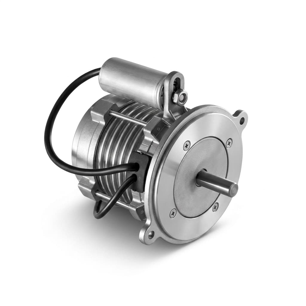
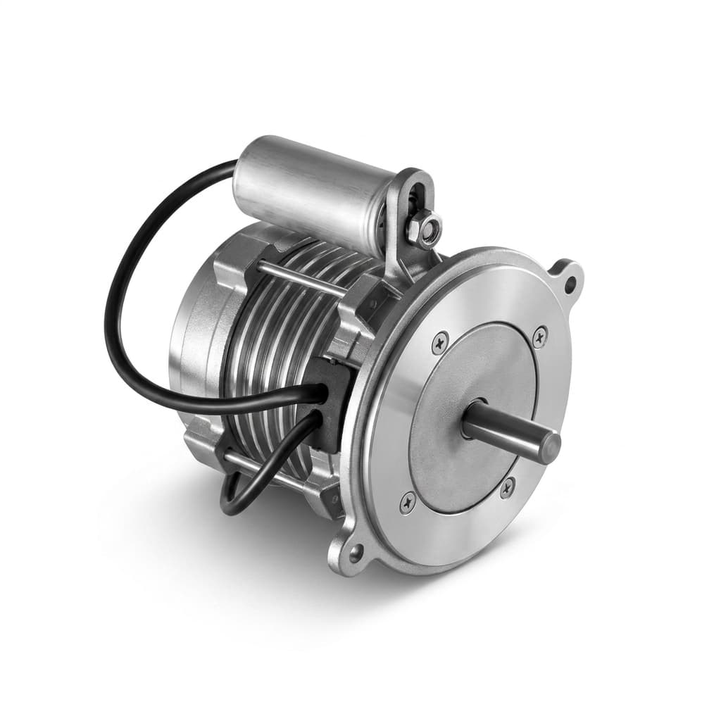
General motor illustration for assembly context. The external view does not identify rotor topology or establish internal bridge geometry, composite sleeve fit or validated burst speed.
For related core specifications, review our guides on thin-gauge electrical steel selection, direct rotor oil cooling architectures, 800V SiC inverter insulation & PDIV, and EESM vs. IPM procurement comparison.
Preparing a high-speed rotor RFQ? Submit your rotor outer diameter, maximum operating speed, and temperature envelope for engineering review.
1. The Centrifugal Mechanics of High-Speed Magnet-Free Rotors
Higher speed can reduce the active volume needed for a given power, but it also increases centrifugal loading. Assess rotor mechanics alongside electrical losses, cooling, bearing limits and critical speeds; rpm alone does not determine feasibility.
The Quadratic Scaling of Centrifugal Acceleration
For rotational speed n in rpm, radius r in metres and angular speed ω in rad/s:
Angular speed:             ω = 2π × n / 60
Tip speed:                 v = ω × r
Centrifugal acceleration:  a_c = ω² × r = v² / r
Radial load on mass m:     F_c = m × ω² × r
For a representative rotor with an outer radius of 0.075 m, or 150 mm outer diameter, the calculations are:
Case 1: 6,000 rpm
  ω = 628.3 rad/s
  Tip speed v = 47.1 m/s
  Centrifugal acceleration a_c = 29,609 m/s² ≈ 3,019 × g

Case 2: 18,000 rpm
  ω = 1,885.0 rad/s
  Tip speed v = 141.4 m/s
  Centrifugal acceleration a_c = 266,479 m/s² ≈ 27,173 × g

Case 3: 24,000 rpm
  ω = 2,513.3 rad/s
  Tip speed v = 188.5 m/s
  Centrifugal acceleration a_c = 473,741 m/s² ≈ 48,308 × g
At 24,000 rpm, a 50-gram segment located at this radius experiences an outward load of:
F_c = 0.050 kg × 473,741 m/s² = 23,687 N ≈ 23.7 kNIf an illustrative rotor carried 8 kg of copper concentrated at the same 75 mm radius, the sum of the magnitudes of its distributed radial loads would be about 3.79 MN. This is not a net lateral force on a balanced rotor: radial force vectors cancel around the circumference. Actual coil loads require the copper mass distribution and each support's tributary load, rather than assigning the entire sum to one ring or rib. Copper inside the outer radius contributes less per unit mass because acceleration scales with radius at fixed speed.
The Self-Weight Centrifugal Hoop Stress Dilemma
For an ideal thin, freely rotating ring, a first screening estimate of hoop stress generated by its own mass is:
σ_self = ρ × v²
ρ in kg/m³, v in m/s, σ_self in Pa
Using assumed densities at the same 200 m/s tip speed illustrates the density contribution. These inputs are not supplier-certified properties:
- Nickel-alloy example, 8,200 kg/m³: Self-stress is 328 MPa. Compare it with temperature-dependent yield and fatigue allowables for the specified product form and heat treatment.
- Titanium example, 4,430 kg/m³: Self-stress is 177.2 MPa, before adding the retained rotor load and fit-induced stress.
- CFRP example, 1,550 kg/m³: Self-stress is 62.0 MPa. Lower density reduces this contribution; it does not remove it. Assembly pre-stress, thermal strain and laminate failure criteria still govern the design.
This thin-ring expression excludes contact pressure, end effects and segmented-core geometry. For equal radius, increasing speed by 20% increases this inertial stress contribution by 44%; a proof-speed multiplier is therefore not a direct measure of burst margin.
2. Rotor Topology Containment Dilemmas: EESM vs. SynRM
Magnet-free architectures present different load paths. A wound rotor carries copper that requires local retention; a reluctance rotor relies on flux-guide segments and connecting steel bridges. An external sleeve does not automatically solve both problems.
Topology A: Externally Excited Synchronous Motors (EESM)
In an EESM, rotor field windings carry direct current to generate excitation flux. Evaluate two separate retention regions:
- Active-length slot retention: Copper loads the slot wedges, pole geometry and insulation interfaces. Request wedge bending, shear and displacement analysis using the actual coil mass distribution. Acceptance depends on available clearances, insulation strain and fatigue, rather than a universal wedge-deflection limit.
- End-turn support: Copper beyond the lamination stack loads its end supports differently from copper inside a slot. Assess end rings, banding, axial restraints and any full-length sleeve as a connected system. A sleeve spanning unsupported end turns needs a qualified load-transfer interface; covering the active core alone does not establish end-turn retention.
Topology B: Synchronous Reluctance Motors (SynRM)
A SynRM rotor uses different magnetic permeance along the d and q axes. Radial ribs and tangential bridges connect the steel flux guides across or around flux barriers. Making these connections thicker generally helps mechanical strength but can increase magnetic leakage and alter saliency.
The electromagnetic question: What torque, power factor and inverter current result from the proposed bridge geometry across the duty map? Saturation, stator design and the enlarged effective magnetic gap from a sleeve all matter. A fixed percentage improvement cannot be inferred from removing bridges.
The mechanical question: What peak stress, fatigue damage and deformation occur at bridge roots and punched edges? Report lamination grade, temperature-dependent strength, burr direction, notch radii and mesh convergence. A 0.5 mm bridge has no stand-alone rpm rating, and a loss-grade designation does not establish its mechanical yield strength.
The sleeved alternative: An external sleeve can enable thinner bridges or a segmented rotor, but the design must also restrain segment movement, transmit torque and control axial retention. Compare the complete sleeved assembly with an optimized bridged rotor before claiming an efficiency or saliency benefit.
3. Retaining Sleeve Material Technologies: CFRP vs. Non-Magnetic Alloys
Compare the finished retaining component and its qualified manufacturing process. Raw fiber strength, room-temperature alloy yield strength and a tube's nominal burst value describe different things.
Carbon-Fiber Reinforced Polymer (CFRP)
Hoop-oriented carbon fibers provide a low-mass tensile load path. Request the cured laminate's fiber volume fraction, winding angles, void assessment, density and hoop-direction properties at the specified temperature and moisture condition. Fiber datasheets alone do not establish sleeve strength. Flat tensile coupons characterized using ASTM D3039/D3039M provide material evidence within that method's scope; representative ring or component testing is needed to relate it to the finished sleeve.
CFRP is approximately non-magnetic, but carbon fibers are electrically conductive. Effective conductivity depends on fiber orientation, contacts, resin and layup. Slotting and inverter harmonics can still produce sleeve losses. Require an anisotropic loss model and thermal validation rather than accepting a zero-loss claim.
Hoop thermal expansion can be much lower than that of the steel core. The resulting mismatch raises hot-state sleeve tension and can reduce cold-state contact pressure. Radial heat conduction, resin creep and interlaminar stresses also need evaluation.
High-Yield Titanium Alloy (Ti-6Al-4V)
Titanium offers lower density than steel or nickel alloys and can reduce the thermal expansion mismatch relative to a hoop-wound CFRP sleeve. Specify product form, heat treatment, minimum properties and inspection requirements at temperature. The approximate density used in Section 1 is only a screening input.
A metallic sleeve is conductive, so evaluate harmonic eddy-current heating using the actual sleeve thickness, active length, field spectrum and cooling conditions. Neither rpm alone nor the word titanium determines a loss in watts or an efficiency penalty. A closer thermal expansion match also does not remove the need to calculate contact pressure and fit tolerances.
High-Strength Nickel Alloy (Inconel 718)
A qualified nickel-alloy ring can be considered where temperature capability and manufacturing constraints favor a metal solution. Its higher density increases self-stress at the same tip speed. Yield, fatigue and thermal properties depend on product form and heat treatment; do not apply one room-temperature value to every ring.
Conductive losses remain a separate design issue. An end-turn ring outside the main active airgap sees different fields and load paths from a full-length active sleeve. Compare location and geometry before rejecting or selecting an alloy based on a material-family label.
4. Engineering Trade-Off and Supplier Evidence Matrix
Use this matrix to make supplier proposals comparable. It deliberately requests evidence instead of assigning universal maximum speeds or production cycle times to material families.
| Decision parameter | Monolithic lamination bridges | Titanium or nickel-alloy ring | Pre-cured CFRP sleeve | Direct-wound CFRP sleeve |
|---|---|---|---|---|
| Speed capability | Bridge stress, fatigue and displacement at specified radius | Combined ring self-stress, retained load and fit | Qualified laminate plus contact analysis | Qualified laminate, winding pre-stress and contact analysis |
| Magnetic effect | Model leakage through bridges | Include ring location and added effective gap | Include non-magnetic sleeve thickness in gap model | Include finished winding thickness in gap model |
| Conductive losses | Evaluate core and bridge losses | Model harmonic eddy currents and cooling | Use anisotropic conductivity; do not assume zero | Use actual layup conductivity; do not assume zero |
| Thermal mismatch | Check core, shaft and joining interfaces | Use grade-specific expansion data | Evaluate hot tension and cold retention | Include cure shrinkage and winding pre-stress |
| Heat removal | Establish stack and shaft heat paths | Model ring conductivity and contact resistance | Measure or obtain radial laminate conductivity | Include resin-rich layers and interface resistance |
| Assembly risk | Burrs, notch roots and stack alignment | Fit damage, distortion and surface condition | Bore scuffing, delamination and insertion force | Tow placement, tension variation and cure effects |
| Dimensional control | Bridge geometry, stack runout and burr height | Ring bore, wall, ovality and installed runout | Bore, wall variation and installed runout | Winding buildup, cured wall and installed runout |
| Production comparison | Tooling, scrap and stack joining | Material, machining, inspection and assembly | Tube cure, inspection, fit and permitted finishing | Winding, cure, inspection and permitted finishing |
| Qualification evidence | Material certificates and geometry-specific FEA | Material allowables, loss analysis and proof test | Representative laminate/ring tests and calibrated NDT | Same tests plus winding and cure records |
| Supplier release records | Drawing revision and stack traceability | Heat number, fit measurements and balance report | Resin/fiber lots, cure, NDT and balance report | Resin/fiber lots, tension/cure logs, NDT and balance report |
An RFQ comparison should quote prototype quantity, annual volume, tooling, scrap assumptions and inspection coverage separately. Request which processes are performed in-house and which use qualified subcontractors; ownership of winding equipment alone does not demonstrate a validated containment system.
For a proposal comparison, send the supplier drawing revision, duty map and proposed retention architecture for review.
5. Thermal Mechanics & CTE Mismatch: The -40°C to +180°C Interference Fit
Treat this temperature range as an example duty envelope, not a rating of every motor or resin. Specify core and sleeve temperatures separately if cooling creates a gradient. An initial radial interference at assembly temperature must survive both the hot, high-load state and the cold retention case.
The Interference Fit Mechanics
Define positive interference as the free core radius exceeding the free sleeve bore radius. A screening compatibility model is:
δ_free(T, ω) = δ_initial + Δδ_thermal + u_core,rotation − u_sleeve,rotation
Δδ_thermal  = r × (α_core − α_sleeve) × ΔT
Here, the rotational displacements are the separate components' free radial growth at the interface, before contact forces are applied. The rotational contribution can increase or decrease interference; its sign cannot be assigned without calculating both members. For a uniform-temperature linear model, define core and sleeve radial compliances per unit pressure as C_core and C_sleeve:
p_contact ≈ max(0, δ_free / (C_core + C_sleeve))
σ_hoop,pressure ≈ p_contact × r / t  [thin-sleeve estimate]
The maximum with zero represents a compression-only interface without adhesive tensile restraint. A segmented core, anisotropic laminate, nonuniform temperature or bonded interface requires a more detailed model. The sleeve's pressure-induced stress must then be combined with self-stress and other loads using appropriate laminate failure criteria.
Reproducible Thermal Expansion Example
Assume an interface radius of 75 mm, assembly at 20°C, steel expansion coefficient of 12.0 µm/(m·K), and CFRP hoop expansion coefficient of 0.5 µm/(m·K). These are illustrative inputs; replace them with qualified batch and temperature-dependent data.
At a uniform 160°C, the temperature rise is 140 K:
Δδ_thermal = 0.075 × (12.0 − 0.5) × 10⁻⁶ × 140
           = 0.00012075 m = 120.75 µm radial growth mismatch
For an idealized rigid core and a hoop modulus of 140 GPa, imposing this whole mismatch on the sleeve gives a thermal tension increment of approximately:
Δσ_hoop ≈ E_hoop × Δδ_thermal / r
        ≈ 140,000 MPa × 0.00012075 / 0.075
        ≈ 225 MPa
This limiting estimate neglects core compliance, laminate coupling and temperature gradients. It is not a prediction of actual interface pressure or a qualified sleeve stress limit.
At -40°C, the change from assembly temperature is -60 K:
Δδ_thermal = 0.075 × 11.5 × 10⁻⁶ × (−60)
           = −0.00005175 m = −51.75 µm
In this example, an initial 70 µm radial interference leaves only 18.25 µm before rotational growth, tolerances, moisture effects or relaxation are included. That arithmetic does not establish a safe fit. Ask the supplier for minimum contact pressure and maximum laminate strain over every specified operating state and tolerance combination. A universal 65 µm interference or 2 MPa contact-pressure threshold cannot replace that analysis.
Drawing + tolerances + temperature-dependent properties
                         |
                         v
Cold start / hot duty / transient overspeed / end-of-life relaxation
                         |
                         v
Check contact pressure, local strain, displacement and fatigue
                         |
                         v
Correlate analysis with representative thermal and spin tests
Resin Glass Transition and Long-Term Temperature Capability
The matrix transfers shear and supports the fiber architecture. Approaching its glass transition temperature can reduce stiffness and increase creep, but the magnitude depends on resin, cure and conditioning. Request the test method, DMA transition criterion, dry and conditioned results, and retained properties at operating temperature.
A project might initially target a measured glass transition temperature 30 K above continuous duty temperature. This is a planning margin, not a universal acceptance rule. It does not qualify transient exposure, long-term aging, oil compatibility or fatigue. Select the cured resin system using those requirements together; do not substitute a different thermal-analysis method without agreeing how its reported transition relates to the design limit.
6. Manufacturing & Assembly Technologies: Pre-Cured Tubes vs. Direct Winding
Both routes need process qualification linked to the finished rotor's acceptance criteria. Request demonstrated dimensional capability and inspection coverage rather than assuming a material family determines cycle time.
Architecture A: Pre-Cured Composite Tube and Controlled Fit
A supplier winds and cures a tube on a mandrel, measures its bore and wall, inspects it, and installs it on the prepared rotor. Depending on the qualified process, installation can use controlled pressing or a temperature-assisted fit.
Qualified tube -> Bore/wall inspection -> Calibrated NDT
                                              |
Prepared rotor -> Controlled installation -> Fit/runout inspection
                                              |
                       Approved finishing -> Balance -> Release records
Pre-inspection separates tube quality from assembly damage. The remaining risks include bore scuffing, lamination-edge damage, insertion-force variation and delamination. Specify lead-in geometry, permissible press force, interface preparation and any adhesive or lubricant compatibility.
Cooling the rotor to aid installation must be qualified against the copper insulation, impregnation resin, adhesive and lamination assembly. Liquid-nitrogen immersion is not a default process. Include condensation control, handling limits and inspection after temperature normalization.
Architecture B: In-Situ Filament Winding
Direct winding applies impregnated tows onto the prepared rotor or a qualified intermediate layer. Controlled tow tension can introduce pre-stress while avoiding axial insertion, but the final state also depends on cure shrinkage and the rotor's thermal history.
Require tension calibration, tow placement records, winding angle, resin content and the actual cure schedule. Confirm that the complete rotor assembly tolerates the cure cycle. Inspect for voids, dry regions and local buildup. If grinding is proposed, the drawing must allow the resulting fiber removal and define the minimum remaining structural wall. No universal skim depth or cure schedule applies to every laminate.
7. B2B Sourcing & Engineering RFQ Checklist
Use this checklist to assign responsibilities and agree measurable acceptance criteria before tooling release. Values in the examples are inputs for discussion, not mandatory standards limits.
Section A: Mechanical Envelope & Rotational Dynamics
- Operating and transient speeds: State continuous speed, dwell time, peak duration, acceleration, duty cycles and credible fault overspeed. Include rotor radius and mass distribution.
- Proof-speed test: Agree the governing specification, test speed, temperature, duration, fixture, instrumentation and post-test acceptance criteria. If the project specifies 1.20 times a 24,000 rpm maximum, the proof speed is 28,800 rpm. The multiplier is an agreed input here, not a universal requirement derived from UNECE R100.
- Separate burst qualification: Distinguish a nondestructive proof spin from a destructive burst test. Agree sample count, test conditions and the acceptance margin independently. A retaining sleeve supports normal rotor loads; it does not by itself certify containment of fragments after rotor failure.
- Balance and rotor dynamics: Select the appropriate balancing procedure for rigid or flexible behavior. For rigid behavior, use ISO 21940-11 with the agreed edition and amendments. Specify correction planes, residual unbalance and machine measurement capability; balancing alone does not demonstrate critical-speed separation.
- Runout and clearance: Set installed sleeve runout, concentricity and displacement limits from the complete airgap tolerance and shaft-deflection budget.
For an illustrative rigid rotor at 24,000 rpm with a selected balance quality grade G1.0, the permissible specific residual unbalance is calculated from angular speed. It is not a constant 1 g·mm/kg:
ω = 2π × 24,000 / 60 = 2,513.3 rad/s
G = 1.0 mm/s
e_per = G / ω = 0.000398 mm = 0.398 µm
For rotor mass m = 10 kg:
U_per = m × e_per = 3.98 g·mm total
Allocate the total to the correction planes using the rotor geometry and the agreed procedure; do not assign the whole allowance independently to each plane.
Section B: Composite Material & Resin Systems
- Traceable constituents: Record fiber grade and sizing, resin batch, storage history, cure revision, winding angles and agreed fiber-volume-fraction tolerances.
- Conditioned resin performance: Specify the glass transition measurement method and criterion, moisture/oil conditioning, temperature exposure and retained mechanical properties.
- Wall and magnetic gap: Agree finished wall thickness from coupled mechanical and electromagnetic calculations, including any finishing allowance and minimum structural wall.
- Hoop properties: Obtain representative cured-laminate tensile data at relevant temperatures. Confirm coupon orientation and the applicability of ASTM D3039/D3039M; agree representative ring/component testing rather than treating flat-coupon strength as a finished-sleeve rating.
Section C: Thermal Mechanics & Interference Validation
- Temperature map: Define core, sleeve and end-turn continuous and transient temperatures, with the assumed cooling boundary conditions.
- Cold retention: Require minimum contact pressure across tolerance extremes, rotational growth and long-term relaxation. Identify how torque and axial loads transfer through the assembly.
- Hot strain and fatigue: Require local laminate strain, interlaminar stress and fatigue evaluation using temperature- and environment-dependent design allowables and agreed knockdowns. Raw fiber ultimate strain is insufficient.
- Thermal durability: Agree cycle count, ramp rate, dwell, fluid exposure and inspection based on the service mission. Compare pre- and post-test fit, dimensions and defects.
Section D: Quality Assurance & Factory Acceptance Testing
- Qualified NDT: Specify calibrated ultrasonic C-scan or another justified method with representative reference defects, demonstrated detection capability and an agreed acceptance map. Ultrasound alone does not directly certify a void-volume percentage without material-specific correlation.
- Shear qualification: If using ASTM D2344/D2344M short-beam testing, define applicable coupons and conditions. Short-beam strength is not interchangeable with the in-plane shear response measured by ASTM D3518/D3518M, and neither automatically defines a ring test.
- Sampling and release: Set destructive qualification and production sampling from the approved quality plan and process capability; do not assume one burst sample per 500 units is sufficient for every program.
- Handover dossier: Request drawing revision, material lots, cure and tension logs, inspection maps, installed dimensions, balancing records and traceable test reports. Identify the party responsible for accepting deviations.
8. Frequently Asked Questions (FAQ)
How much does a carbon-fiber sleeve increase the effective magnetic airgap?
A near-unity-permeability sleeve adds approximately its radial thickness to the magnetic gap between the steel rotor and stator, in addition to mechanical running clearance. For an illustrative 0.9 mm wall and 0.6 mm running clearance, that radial distance is 1.5 mm before other non-magnetic layers or slotting corrections. These dimensions are not an approved clearance specification. Recalculate magnetizing current, torque, power factor and losses; reduced bridge leakage does not automatically compensate for a larger gap.
Why not use a titanium sleeve if it matches steel thermal expansion better?
It can be a suitable option. Compare its density, qualified mechanical properties, assembly process and temperature capability with CFRP. The closer thermal expansion match may simplify fit design, while electrical conductivity introduces harmonic-loss questions. Request loss estimates for the actual stator slotting and inverter spectrum, together with the resulting sleeve temperature. No universal kilowatt loss or percentage efficiency penalty can be inferred from the alloy name or operating speed.
Can direct rotor oil cooling be combined with a carbon-fiber retaining sleeve?
Yes, if the composite, sizing, resin and any adhesive are qualified in the actual fluid at the intended temperature and duration. Agree allowable changes in dimensions, mass and retained properties after aging. Low radial laminate conductivity may make internal shaft or core cooling attractive, but external spray cooling is not categorically excluded. Compare complete thermal paths and contact resistances with a coupled thermal model and test results.
How is the sleeve outer diameter finished before dynamic balancing?
Use the qualified drawing and process plan. Some assemblies require controlled finishing after installation; others can meet the specified geometry without it. If grinding is allowed, specify the sacrificial layer, minimum remaining structural wall, surface damage limits and post-process inspection. Removing an arbitrary depth of load-carrying fibers can invalidate the structural analysis. Verify installed runout separately from residual unbalance: dimensional concentricity and dynamic balance are different acceptance checks.
What failure mechanisms should a qualification plan investigate?
Investigate loss of interface pressure, excessive hot-state laminate strain, matrix creep, environmental degradation, assembly damage and fatigue under the mission profile. Also examine coil/end-turn support and local stresses at segmented-core interfaces. These are engineering failure hypotheses, not a claim that this publisher has observed particular failures on a dyno. Correlate inspection findings with recorded speed, temperature and vibration before assigning a root cause.
Is external rotor sleeving always required for SynRM motors?
No. An adequately designed bridged rotor may meet the mechanical and electromagnetic requirements without a sleeve. Radius, speed, flux-barrier geometry, steel properties, fatigue duty and manufacturing quality determine suitability. There is no universal 140–160 m/s threshold that mandates sleeving. Compare validated architectures at the same torque-speed map, thermal conditions, inverter constraints and acceptance criteria.
9. Sourcing Strategy & RFQ Preparation
Specifying high-speed rotor containment requires treating the rotor core, sleeve, and dynamic balancing as an integrated structural system rather than assembling off-the-shelf components.
When preparing your RFQ:
- Define the complete speed-torque envelope: Include continuous rated speed, transient overspeed, maximum acceleration rates (rad/s²), and overspeed qualification standards.
- Conduct coupled thermal-mechanical FEA: Model radial interference pressure across the full -40°C to +180°C operating spectrum before freezing drawing tolerances.
- Audit Tier-1 composite winding capabilities: Confirm demonstrated process capability, calibrated inspection and access to qualified spin-test and balancing facilities, including any approved subcontractors.
Sources & Engineering Standards
- ISO 21940-11:2016 — Mechanical vibration — Rotor balancing — Part 11: Procedures and tolerances for rotors with rigid behaviour. The official ISO catalogue record identifies the rigid-rotor balancing standard and an amendment. Agree the applicable edition and amendments; this scope does not qualify flexible-rotor dynamics or sleeve burst strength.
- ASTM D3039/D3039M — Standard Test Method for Tensile Properties of Polymer Matrix Composite Materials. The official ASTM record for the 2017 edition describes in-plane tensile-property measurement and identifies that edition as historical, with a 2025 reapproval listed. Specify the contractual edition and representative material conditioning. A coupon method does not itself establish finished-ring acceptance or a universal 2,200 MPa allowable.
- IEC 60034-1:2026 — Rotating electrical machines — Part 1: Rating and performance. The official IEC catalogue record identifies this edition as replacing 2022. Its scope excludes rotating machines for rail and road vehicles and points to the IEC 60349 series. Confirm applicability for the actual industrial or traction program; this guide does not infer a universal automotive 1.2× proof-speed requirement from it.
Catalogue metadata checked November 5, 2026 using official publisher records and their indexed descriptions; direct retrieval of some publisher pages was restricted. Full paid standards were not reviewed. The arithmetic uses thin-ring and simplified radial-compatibility models with stated assumptions. Material allowables, production acceptance limits and compliance require project-specific evidence.
Need Engineering Support for High-Speed Magnet-Free Motor Sourcing?
Discuss your high-speed rotor containment, hollow-shaft machining, and lamination stamping requirements with the Magnet-Free Motor engineering team.
- Synchronous Reluctance Motors: Review our IE5 SynRM product catalog and traction motor supplier guide.
- Wound-Rotor Systems: Explore our WRSM/EESM product portfolio and EESM rotor assembly solutions.
- Core Laminations: Review our thin-gauge lamination stack capabilities.
- Submit Requirements: Send your rotor dimensions, target rpm, and thermal boundary conditions for a detailed engineering feasibility review and formal quotation.
Author

More Posts
IE5 SynRM vs. Induction Motors: A Comprehensive Efficiency Comparison
An engineering deep dive comparing IE5 Synchronous Reluctance Motors (SynRM) against traditional induction motors for heavy-duty industrial applications.

Thin-Gauge Electrical Steel Selection for High-Frequency Magnet-Free Motors: NO20, NO25, and Stacking Tech RFQ Guide
Compare NO20 and NO25 thin-gauge electrical steel for magnet-free motors. Review loss data, joining trade-offs, and the RFQ checklist before requesting a quote.
The Industry Shift to Rare-Earth-Free Traction Drives: Lessons from Global EV Leaders
Global automakers are moving away from rare-earth permanent magnets. Explore the engineering behind the new wave of magnet-free EV traction motors.