
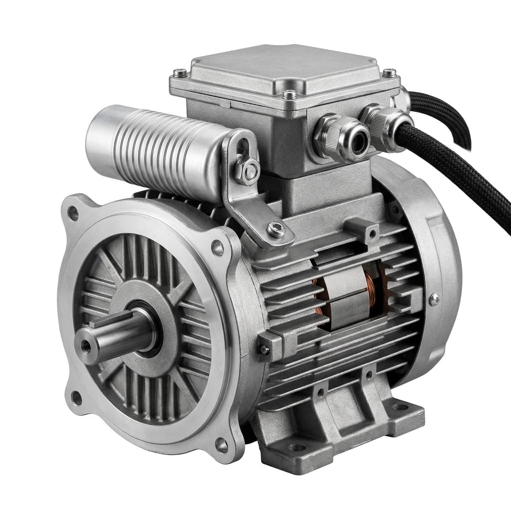
Understanding Switched Reluctance Motors (SRM) for Harsh Environments
Explore the robust architecture of Switched Reluctance Motors (SRM) and why they excel in extreme temperatures, high vibration, and harsh industrial settings.
Understanding Switched Reluctance Motors (SRM) for Harsh Environments
The short answer: Switched Reluctance Motors operate reliably in ambient temperatures from -40°C to +200°C, withstand continuous vibration up to 20g, and provide inherent fault tolerance through independent phase operation. Their solid-steel rotor contains zero magnets or windings, making them the most mechanically rugged motor architecture available for mining, oil & gas, steel processing, and defense applications.
When designing machinery for the world's most unforgiving environments—such as deep-shaft mining equipment, high-temperature steel mills, or heavy-duty agricultural machinery—traditional electric motors frequently fail. Induction motors burn out under constant high-load stalling, while permanent magnet (PM) motors suffer from catastrophic demagnetization at elevated temperatures.
The Switched Reluctance Motor (SRM). Built entirely without magnets and featuring a rotor made of solid steel, the SRM is one of the most rugged, fault-tolerant motor architecture ever engineered.
SRM vs. Competing Architectures: Environmental Ratings
| Environmental Factor | ACIM (Induction) | PMSM (Permanent Magnet) | SRM (Switched Reluctance) |
|---|---|---|---|
| Max ambient temperature | 40–55°C (Class F/H) | 40–55°C (magnet limit) | 80–200°C (no magnets) |
| Min ambient temperature | -20°C | -30°C | -40°C |
| Vibration resistance | 5–10g | 5–8g | 15–20g |
| Shock tolerance | 15–30g | 10–20g | 50–100g |
| Dust/particle ingress | IP55–IP65 | IP55–IP65 | IP67–IP68 possible |
| Chemical resistance | Moderate | Low (magnet coating risk) | High (no magnets to corrode) |
| Stall tolerance | Minutes (thermal limit) | Seconds (demagnetization risk) | Continuous at rated current |
| Fault tolerance (phase loss) | Motor stalls | Motor stalls with drag | Continues running |
Why the Rotor is So Simple
The reason for the SRM's durability lies in its mechanical simplicity.
- No Rotor Windings or Magnets: The rotor is simply a piece of stamped, laminated electrical steel with protruding poles. There are no copper bars, no permanent magnets, and no slip rings.
- Concentrated Stator Windings: The stator features concentrated copper coils wrapped around independent salient poles.
Torque is generated by sequentially switching the current in the stator coils. The steel rotor poles naturally align with the energized stator poles to minimize magnetic reluctance.
Why SRM Excels in Extreme Conditions
1. Immunity to Extreme Heat
In a PM motor, high temperatures (often exceeding 150°C) can cause irreversible demagnetization of the Neodymium magnets, permanently destroying the motor. Because the SRM has no magnets, it is entirely immune to this failure mode. On top of that, because there are no rotor currents (unlike induction motors), almost all heat is generated in the stator, where it is easily dissipated through the outer cooling fins or water jacket.
Temperature Derating Comparison
| Ambient Temperature | PMSM Available Torque | ACIM Available Torque | SRM Available Torque |
|---|---|---|---|
| 25°C (standard) | 100% | 100% | 100% |
| 55°C | 90% | 92% | 98% |
| 80°C | 75% (demagnetization risk) | 80% | 95% |
| 120°C | FAILED (magnets destroyed) | 60% (insulation limit) | 85% |
| 150°C | FAILED | FAILED | 70% (Class H insulation) |
| 200°C | FAILED | FAILED | 55% (special insulation) |
2. High-Speed Durability
Rotors with embedded magnets or copper cages are subject to immense centrifugal forces at high RPMs, risking mechanical disintegration. The solid steel block rotor of an SRM can withstand extreme rotational speeds, making it ideal for high-speed centrifugal compressors and blowers.
Rotor Tip Speed Limits
| Motor Type | Max Safe Rotor Tip Speed | Limiting Factor |
|---|---|---|
| Surface PM (SPM) | 120–150 m/s | Magnet retention sleeve |
| Interior PM (IPM) | 150–200 m/s | Bridge saturation stress |
| Copper cage (ACIM) | 150–180 m/s | Bar/end-ring fatigue |
| SRM (solid steel) | 200–250 m/s | Steel yield strength only |
3. Unmatched Fault Tolerance
In an SRM, each stator phase is electrically and magnetically independent. If one phase winding shorts or a power electronics switch fails, the motor does not catastrophically lock up. The controller can simply disable the damaged phase, and the motor will continue to operate at a reduced torque capacity.
Fault Tolerance Comparison
| Fault Scenario | ACIM Response | PMSM Response | SRM Response |
|---|---|---|---|
| Single phase open | Motor stalls | Motor stalls | Continues at ~67% torque |
| Single phase short | Heavy vibration, burns | High drag torque | Continues, fault isolated |
| Power switch failure (IGBT) | Motor stalls | Motor stalls | Continues on remaining phases |
| Bearing seizure | Locks up | Locks up | Locks up (same) |
| Coolant loss | Rapid overheat | Demagnetization | Extended operation (no magnets) |
This "limp-home" capability is vital for mission-critical aerospace, defense, and heavy mining applications.
Industrial Application Mapping
| Industry | Application | Why SRM Wins | Operating Conditions |
|---|---|---|---|
| Mining | Conveyor drives, crushers | Stall tolerance, dust immunity | 50–80°C, 10g vibration |
| Oil & Gas | Downhole pumps, compressors | High temperature, fault tolerance | 120–180°C, explosive atmosphere |
| Steel mills | Roller drives, hot zone transport | Extreme ambient heat | 80–200°C radiant heat |
| Defense | Turret drives, vehicle propulsion | Fault tolerance, ruggedness | -40 to +70°C, 50g shock |
| Aerospace | Fuel pumps, actuators | High-speed, zero-magnet safety | Altitude, temperature cycling |
| Agriculture | Harvester drives | Dust, vibration, stall conditions | Seasonal extremes |
Overcoming the NVH Challenge
Historically, the primary drawback of SRM technology has been Noise, Vibration, and Harshness (NVH). The aggressive switching of magnetic fluxes causes the stator core to flex, generating acoustic noise.
NVH Mitigation Techniques
| Technique | NVH Reduction | Implementation Complexity |
|---|---|---|
| Current profiling (soft switching) | -6 to -10 dB | Control software update |
| Stator/rotor skewing | -3 to -6 dB | Tooling modification |
| Random PWM switching | -4 to -8 dB | Inverter firmware |
| Stator damping rings | -2 to -4 dB | Mechanical addition |
| Optimized pole geometry | -4 to -7 dB | FEA redesign |
| Active vibration cancellation | -8 to -12 dB | Advanced control + sensors |
Modern advancements in power electronics and advanced control algorithms—such as Direct Torque Control (DTC) and advanced current profiling—have significantly smoothed the torque ripple. Today, OEM manufacturers utilize sophisticated finite element NVH modeling and dynamic skewing to produce SRMs that rival the quiet operation of traditional architectures.
FMEA: Switched Reluctance vs. Legacy Architectures
A Failure Mode and Effects Analysis (FMEA) demonstrates why SRM is the strongest option for mission-critical industrial applications:
| Failure Mode | AC Induction Motor (ACIM) | Permanent Magnet Motor (PMSM) | Switched Reluctance Motor (SRM) |
|---|---|---|---|
| Extreme Overheating (above 150°C) | Insulation breakdown, rotor bar melting | Catastrophic (Magnets irreversibly demagnetize) | Immune (Solid steel rotor survives) |
| Single Phase Fault / Short Circuit | Motor stalls, heavy vibration, burns out | Motor stalls, high drag torque | Limp-Home Mode (Continues running on remaining phases) |
| High Centrifugal Stress (Overspeed) | Rotor cage deformation | Magnet retention sleeve failure | Immune (No moving parts on rotor to fail) |
| High Vibration / Shock Load | Moderate risk of winding failure | Magnets chip/crack | Highly Resilient |
Summary
For procurement teams outfitting heavy industry, the total cost of ownership extends far beyond the purchase price. By virtually eliminating thermal degradation and mechanical rotor failures, Switched Reluctance Motors provide a zero-maintenance, highly ruggedized solution for environments where failure is not an option.
The key buyer decision factors for SRM:
- If ambient temperature exceeds 80°C: SRM is the only viable architecture
- If fault tolerance is mission-critical: SRM's independent phase operation is unmatched
- If rare-earth supply chain risk is unacceptable: SRM uses zero permanent magnets
- If NVH is a primary concern: Modern control techniques have largely solved this, but verify noise specs in the RFQ
References
- IEEE Transactions on Industrial Electronics — Comprehensive surveys on SRM torque ripple reduction and NVH mitigation are published regularly in this journal. Search IEEE Xplore for "switched reluctance motor torque ripple".
- IEC 60034-5 — Protection levels (IP codes) for rotating electrical machines, relevant to harsh environment specifications.
- ISO 1940-1 — Balance quality requirements for rigid rotors, referenced for SRM rotor balance grades.
Related Reading
- Why Magnet-Free Motors Are the Future of Industrial Automation — How SRM fits into the broader magnet-free architecture family.
- Rare Earth Price Forecast 2026 — The supply chain economics driving adoption of zero-magnet designs.
- How to Audit a Motor Manufacturer — Qualification criteria for SRM suppliers.
Author

Categories
More Posts
The Industry Shift to Rare-Earth-Free Traction Drives: Lessons from Global EV Leaders
Global automakers are moving away from rare-earth permanent magnets. Explore the engineering behind the new wave of magnet-free EV traction motors.
IE5 Motor Efficiency Standards Explained: Do You Need Magnets to Comply?
Understand the IE5 Ultra-Premium Efficiency standard. Learn how Synchronous Reluctance Motors (SynRM) achieve IE5 compliance without rare-earth magnets.
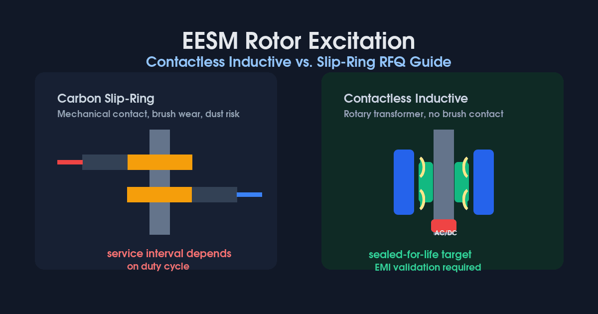
Contactless vs. Slip-Ring EESM Excitation: 2026 RFQ Guide
Compare contactless inductive and carbon slip-ring excitation for EESM. Use 2026 TCO, RPM, EMI, cooling, and supplier checks before issuing an RFQ.