
The Role of Hairpin Winding in High-Performance EV Traction Motors
Learn why automated hairpin winding technology is essential for maximizing power density and thermal efficiency in next-generation EV traction motors.
The Role of Hairpin Winding in High-Performance EV Traction Motors
The short answer: Hairpin (flat-wire) stator winding achieves 70–78% slot fill factor versus 40–45% for round wire, enabling 15–30% higher continuous power density in the same motor envelope. For EV traction programs targeting ≥30 kW/L power density, hairpin winding is now the industry standard manufacturing process.
The transition to electric mobility has pushed motor engineering to its absolute limits. Automakers and tier-1 suppliers demand motors that are smaller, lighter, and vastly more powerful than ever before. To achieve these extreme power densities—while simultaneously moving away from rare-earth permanent magnets—manufacturers are rapidly adopting Hairpin Winding Technology.
Hairpin winding replaces traditional round-wire random winding. In this article, we explore how flat-wire hairpin stators are becoming standard practice in EV traction motor manufacturing.
What is Hairpin Winding?
Traditional stators are wound using bundles of thin, round enameled copper wires pulled through the stator slots. Because the wires are round and randomly distributed, there is a significant amount of "dead space" (air) between them.
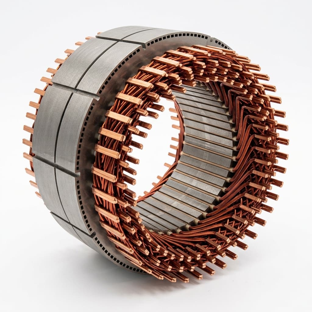
Hairpin winding, conversely, uses thick, rectangular copper conductors bent into a "U" or hairpin shape. These rigid conductors are precisely inserted into the stator slots, laser-welded at the ends, and tightly packed.
Round Wire vs. Hairpin: Quantitative Comparison
| Parameter | Round Wire | Hairpin Wire | Improvement |
|---|---|---|---|
| Slot fill factor | 40–45% | 70–78% | +65–75% |
| Continuous power density | 15–22 kW/L | 28–45 kW/L | +60–100% |
| Phase resistance (at same current) | Baseline | -25 to -35% | Significant |
| Thermal conductivity (slot to jacket) | 1.5–3 W/m·K | 8–15 W/m·K | +400–500% |
| End-winding axial length | Baseline | -20 to -30% | Shorter motor |
| Manufacturing repeatability (Cpk) | 1.0–1.3 | 1.5–2.0 | Higher consistency |
| Typical production speed | 3–8 min/stator | 1.5–4 min/stator | 2x faster |
1. Maximizing Slot Fill Factor
The most immediate benefit of hairpin technology is the Slot Fill Factor—the percentage of the stator slot area actually occupied by copper.
- Round Wire: Typically achieves a slot fill factor of 40% to 45%.
- Hairpin Wire: Can achieve a slot fill factor exceeding 70%, with advanced 6-layer designs reaching 75–78%.
By packing more copper into the same volume, the motor's electrical resistance is significantly reduced. This allows the motor to carry significantly higher currents, resulting in a significant increase in continuous power density.
Slot Fill Impact on Key Performance Metrics
| Slot Fill Factor | DC Resistance Reduction | Peak Torque Gain | Continuous Power Gain |
|---|---|---|---|
| 45% (round wire) | Baseline | Baseline | Baseline |
| 60% (basic hairpin) | -18% | +12% | +15% |
| 70% (standard hairpin) | -30% | +20% | +25% |
| 78% (optimized 6-layer) | -38% | +25% | +32% |
2. Superior Thermal Management
Heat is the primary constraint of an electric motor. In a traditional round-wire stator, the air gaps between the wires act as thermal insulators, trapping heat deep within the slot.
Rectangular hairpin conductors lay flat against each other and flat against the stator slot liner. This creates a highly efficient, continuous thermal conduction path from the center of the winding directly out to the cooling jacket. Improved heat dissipation allows the motor to operate at higher peak loads for longer durations without thermal derating—a critical metric for EV acceleration and highway cruising.
Thermal Performance Data
| Metric | Round Wire Stator | Hairpin Stator |
|---|---|---|
| Peak winding temperature (at rated load) | 155–180°C | 120–145°C |
| Time to thermal limit (peak torque) | 15–30 seconds | 45–90 seconds |
| Continuous current derating at 40°C ambient | 85–90% | 95–100% |
| Hot-spot temperature differential (Δ from average) | 25–40°C | 8–15°C |
3. High-Volume Automation
Hairpin winding is inherently suited for high-volume production. Unlike round-wire winding, which often involves complex, slow-moving needle winding machines and manual manipulation, hairpin manufacturing is a highly structured, robotic process.
Manufacturing Process Flow
| Step | Process | Key Equipment | Quality Gate |
|---|---|---|---|
| 1 | Wire stripping & cutting | CNC flat-wire cutter | Conductor dimension ±0.02mm |
| 2 | 3D forming (bending) | Multi-axis CNC bender | Bend angle ±0.5°, leg length ±0.3mm |
| 3 | Insulation coating | Electrostatic powder coating | Coating thickness 40–80μm, pinhole test |
| 4 | Slot insertion | Robotic insertion station | Insertion force monitoring, slot liner integrity |
| 5 | Crown spreading & twisting | Automated twist fixture | Twist angle ±1°, conductor spacing check |
| 6 | Laser welding | Fiber laser welder + AOI | Weld depth 0.8–1.2mm, resistance ≤50μΩ |
| 7 | Insulation & VPI | Vacuum Pressure Impregnation | Gel time, cure temperature, void inspection |
| 8 | End-of-line test | Hipot + surge + resistance | Phase resistance balance ±2%, hipot 2.5kV |
At Magnet-Free Motor, hairpin stator programs are reviewed around slot-fill target, bend repeatability, weld resistance, insulation clearance, and the validation records required before pilot or production release.
Laser Welding: The Critical Process Control Point
The most quality-sensitive step in hairpin manufacturing is the laser welding of conductor ends. A single weak weld can cause localized overheating and eventual motor failure.
Weld Quality Acceptance Criteria
| Parameter | Acceptance Range | Test Method |
|---|---|---|
| Weld nugget depth | 0.8–1.2mm (or 60–80% of conductor cross-section) | Cross-section metallographic analysis |
| Joint resistance | ≤50 μΩ per joint | 4-wire Kelvin micro-ohm measurement |
| Porosity | ≤5% void area in weld zone | X-ray or CT inspection (sampling) |
| Heat-affected zone (HAZ) | ≤0.3mm beyond weld boundary | Metallographic analysis |
| Insulation clearance post-weld | ≥0.5mm to adjacent conductor | Optical measurement |
| Surge withstand | ≥3.5kV inter-turn | Surge tester at EOL |
Addressing the High-Frequency AC Loss Challenge
While hairpin winding is superior, it has trade-offs. Thick rectangular conductors are susceptible to skin effect and proximity effect at high switching frequencies, which can cause AC copper losses at very high speeds.
AC Loss Mitigation Strategies
| Strategy | Effect | Trade-off |
|---|---|---|
| Reduce conductor height | Reduces skin depth ratio | Slightly lower slot fill |
| Increase number of layers (4→6→8) | Reduces proximity effect | More complex insertion/welding |
| Conductor transposition | Equalizes current distribution | Adds manufacturing steps |
| Segmented conductors | Breaks eddy current loops | Increases joint count |
| Optimize inverter switching frequency | Reduces harmonic content | May affect torque smoothness |
As the industry pivots to 800V architectures and magnet-free WRSM (Wound Rotor Synchronous Motor) designs, hairpin winding is the foundational technology that makes high-performance, rare-earth-free EVs a reality.
Buyer's Qualification Checklist for Hairpin Stator Suppliers
Before placing an RFQ for hairpin stator assemblies, ensure the supplier can demonstrate:
- Bend repeatability: Cpk ≥1.67 on critical bend dimensions
- Weld quality data: Statistical weld resistance data across 500+ consecutive joints
- AOI integration: 100% automated optical inspection on every weld, not sampling
- VPI cycle validation: Documented cure profile with thermocouple data
- Phase resistance balance: ±1.5% or better across all phases
- Hipot/surge test: 100% end-of-line with recorded results per serial number
- Traceability: Copper lot → conductor → stator serial number linkage
References
- SAE International 2020-01-0471 — Technical paper on hairpin winding manufacturing challenges for automotive traction motors.
- IEC 60317 — Specifications for particular types of winding wires, including rectangular enameled copper.
- ISO 1940-1 — Balance quality requirements referenced for rotor and stator assembly specifications.
Related Reading
- How to Audit a Motor Manufacturer — What to verify on a hairpin production line during a factory visit.
- EESM vs. IPM Motors: Procurement Comparison — Where hairpin stators fit in the EESM vs. IPM decision.
- The Industry Shift to Rare-Earth-Free Traction — How hairpin winding enables high-volume magnet-free EV production.
Author

Categories
More Posts
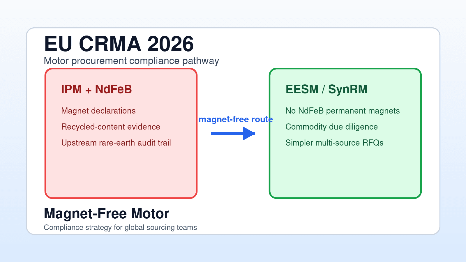
EU CRMA 2026: Why Magnet-Free Motors Are the Safest Compliance Strategy
How the EU Critical Raw Materials Act (CRMA) affects 2026 motor procurement. Compare NdFeB tracking overhead against magnet-free EESM and SynRM alternatives.
Rare Earth Price Forecast 2026: Why Motor Manufacturers are Abandoning Neodymium
A deep dive into the 2026 rare-earth pricing forecast. Learn why volatile Neodymium and Dysprosium markets are forcing OEMs to adopt magnet-free motors.
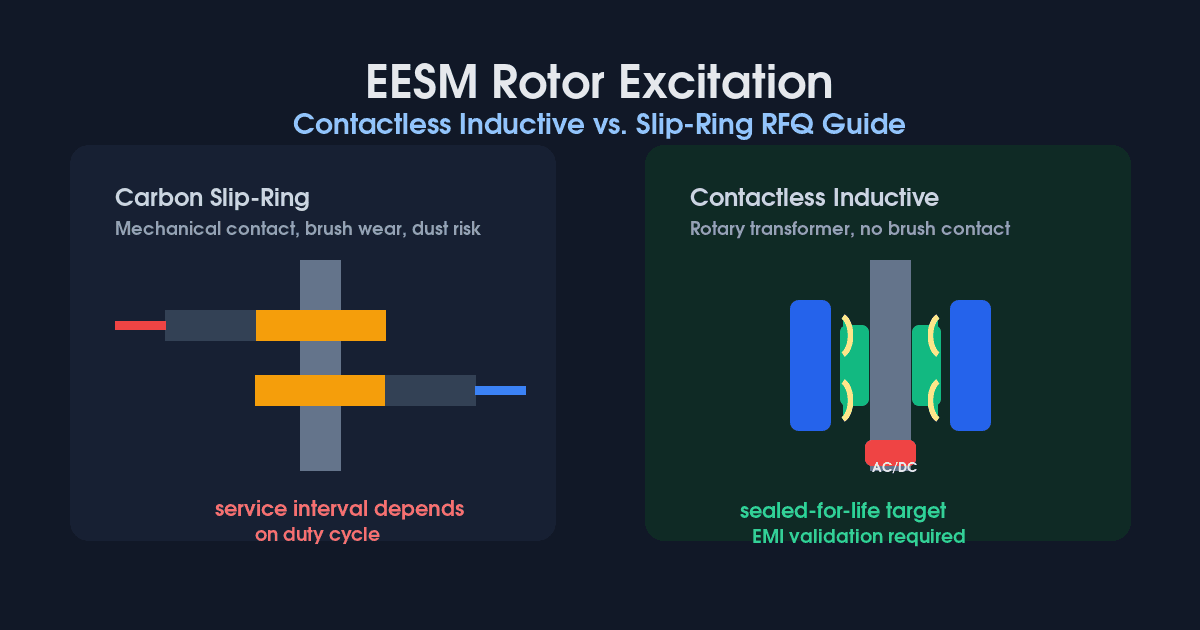
Contactless vs. Slip-Ring EESM Excitation: 2026 RFQ Guide
Compare contactless inductive and carbon slip-ring excitation for EESM. Use 2026 TCO, RPM, EMI, cooling, and supplier checks before issuing an RFQ.